The communication is established to the satellite through earth station. The earth station can be located on the ship at the sea, or it can be located on the space craft or actually on the earth.
The location of the earth station is decided depending upon the ease of control of satellite and the function of the satellite.
The type of earth station depends upon the (a) function of the station, (b) type of service, (c)frequency bands used, (d) transmitters, (e) receiver and (f) antenna characteristics. The four major subsystems of any earth station are, receiver, antenna, transmitter and tracking equipment.
The special earth stations like TVRO (TV receiver only or direct broadcast satellite receivers) does not have transmitting function. Some other earth stations are very special, like tracking and control of satellite.
Fig shows the basic block diagram of a satellite earth station.
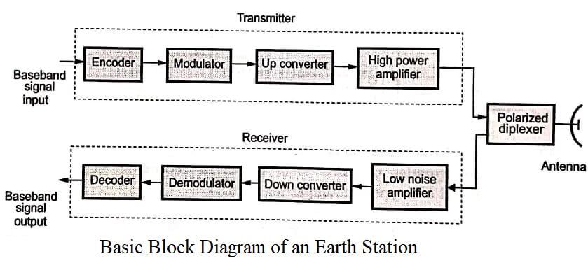
The baseband signal is applied to the encoder. Encoder converts the format ready for modulation. The carrier is modulated by the encoded baseband signal.
The modulated carrier is then upconverted to the uplink frequency of the satellite. The amplifier then amplifies this signal to high power level, ready for transmission.
The signal is then passed through the polarization feed of the antenna. The signal received from the antenna is of different frequency (downlink frequency) and is very small in amplitude. This signal is amplified by the low noise amplifier.
It is then down converted to the intermediate frequency by the down converter. This signal is then demodulated and decoded to get baseband signal.
Now let us discuss the earth station subsystems in detail.
Transmitter Section
In the large earth stations many channels are required to be transmitted. The amplifiers used are High Power Amplifiers (HPAs). These amplifiers have wide bandwidth at microwave frequencies.
These amplifiers are normally klystron or Travelling Wave Tubes (TWT) based. The power capacity of these amplifiers varies from 500 to 2000 watts.
Fig shows the block diagram of transmitter section of the earth station.
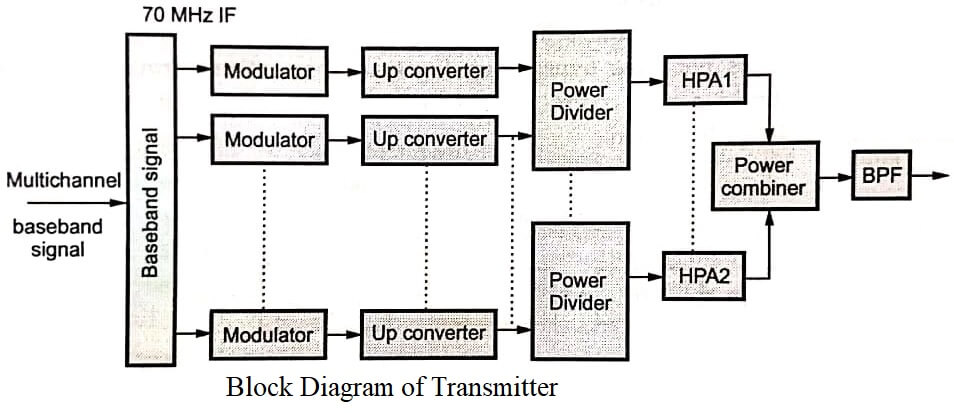
The outputs of the HPA are combined through bandpass filters. The 70 MHz IF is upconverted. The configuration of HPAs to be employed depend on the number of carriers to be transmitted and type of multiplexing used.
Receiver Section
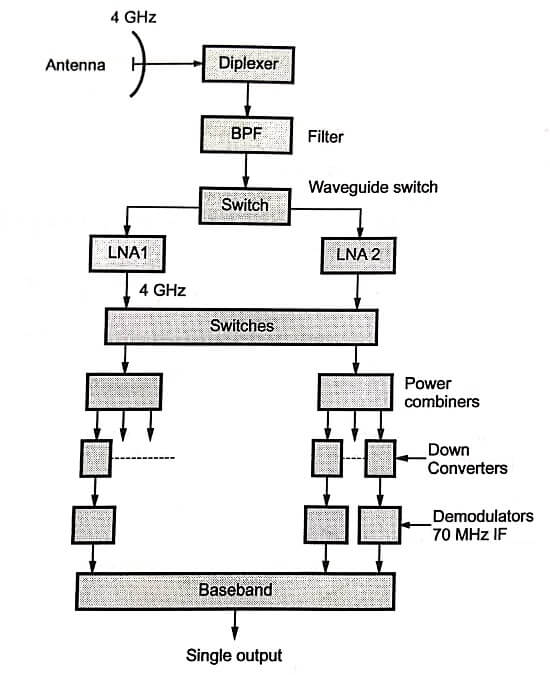
Fig shows the receiver section of the earth station. The receiver has low noise amplifier (LNA), down converter, demodulator, decoder and baseband signal treatment equipment.
Normally the same antenna diplexer separates the downlink and uplink frequencies at the earth stations. The first stage of the receiver should have very low noise and sufficiently high gain. The Low Noise Amplifiers (LNAs) cover 500 MHz band.
| Read More Topics |
| Code division multiple access |
| Frequency reuse by dual polarization |
| Orbital aspects of satellite communication |
