Definition of Straightness of a Line in Two Planes
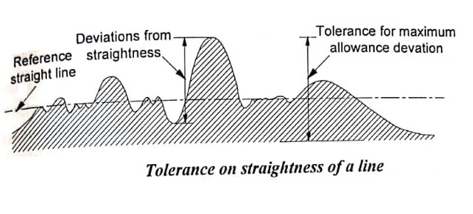
A line is said to be straight over a given length, if the variation of the distance of its from two planes perpendicular to each other and parallel to the general direction of the line remains within the specified tolerance limits. The tolerance on the straightness of a line is defined as the maximum deviation in relation to the reference straight line joining the two extremities of the line to be checked. Fig shows the tolerance on straightness measurement of a line.
Straight edge:
A straight edge is a measuring tool which consists of a length of a steel of narrow and deep section in order to provide resistance to bending in the plane of measurement without excessive weight.
For checking the straightness measurement of any surface, the straight edge is placed over the surface and two are viewed against the light, which clearly indicates the straightness.
The gap between the straight edge and surface will be negligibly small for perfect surfaces. Straightness is measured by observing the colour of light by diffraction while passing through the small gap. If the colour of light is red, it will indicate a gap of 0.0012 to 0.0075mm.
A more accurate method of finding the straightness by straight edges is to place it an equal slip gauges at the correct point for minimum deflection and to measure the uniformity of space under the straight edge with slip gauges.
Test for Straightness by Using Spirit Level and Autocollimator
The straightness of any surface could be determined by either of these instruments by measuring the relative angular positions of number of adjacent sections of the surface to be tested.
First, a straight line is drawn on the surface and then it is divided into a number of sections. The length of each section is equal to the length of sprit level base or the plane reflector’s base in case of auto collimator.
The base of the spirit level block or reflector are fitted with two feet so that only feet have line contact with the surface and the surface of base does not touch the surface to be tested. The angular division is obtained between the two specified points. Length of each section must be equal to the distance between centerlines of two feet.
The spirit level can be used only for the measurement of straightness of horizontal surfaces while auto collimator can be used on surfaces in any plane.
In case of spirit level, the block is moved along the line equal to the pitch distance between the centerline of the feet and the angular variation of the direction of block. Angular variation can be determined in terms of the difference in height between two points by knowing the least count of level and length of the base.
In case of autocollimators, the instrument is placed at a distance of 0.5 to 0.75m from the surface to be tested. The parallel beam from the instrument is projected along the length of the surface to be tested. A block fixed on two feet and fitted with a plane vertical reflector is placed on the surface and the reflector face is facing the instrument. The image of the cross wires of the collimator appears nearer the center of the field and for the complete movement of reflector along the surface straight line the image of cross wires will appear in the field of eyepiece. The reflector is then moved to the other end of the surface in steps equal to the center distance between the feet and the tilt of the reflector is noted down in second from the eyepiece. The straightness measurement testing is shown in image.
1 second of arc = 0.000006mm/mm
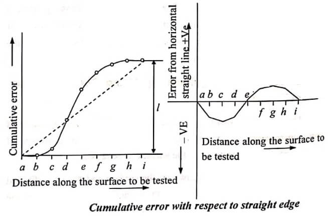
Therefore, 1 second of arc will correspond to a rise or fall of 0.000060mm. Where λ is the distance between centers of feet in mm. With the reflector set at a -b, the micrometer reading is noted and this line is treated as datum line. Successive readings at b – c, c – d, d – e etc are taken till the length of the surface to be tested has been stepped along.
In order to eliminate error in previous set of readings, the second set of readings could be taken by stepping the reflector in the reverse direction and the mean of two taken. The mean reading represents the angular position of the reflector in seconds relative to the optical axis of auto collimator.
The errors of any surface may be relative to any mean plane. It is assumed that the mean plane is one joining the end points then whole of graph must be swing round until the end point is on the axis. The fig shows the cumulative error and the error with respect to straight edge.
- See More : Measurement of screw thread
- See More : Methods of measuring surface finish
- See More : Measurement of various elements
- See More : Definition of metrology


