Three phase induction motors are extensively used for electric drives. The main advantages which make it so popular for industrial use are:
- It is simple and extremely rugged construction.
- High reliability.
- Low cost.
- Its ability to start off from rest unlike synchronous motors which have to be started and run up by separate prime movers.
- High efficiency.
- It requires little maintenance.
The disadvantages of induction motors are
- The speed is not constant, when load is varied.
- Low starting torque compared to DC shunt motor.
- Reduction in efficiency when speed is varied.
Construction
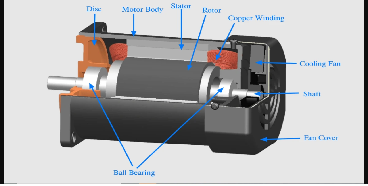
Three Phase Induction Motors consists of two main parts viz (a) stator (b) rotor
Stator
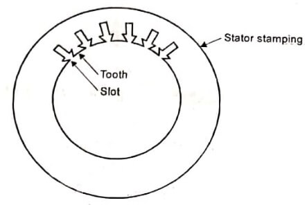
The stator is made up of a number of stampings with alternate slot and tooth. Stampings are insulated from each other. Each stamping is 0.4 to 0.5 mm thick. Number of stampings are stamped together to build the stator core.
The stator core is then fitted in a casted or fabricated steel frame. The slow house the three phase winding just like the three-phase alternator. The three-phase winding is called stator winding. It may be connected either in star or delta. The stator winding is made for a fixed number of poles. Figure shows the stator lamination.
Rotor
There are two types of rotors used in induction motors. They are
- Squirrel cage rotor
- Slip ring or wound rotor
Squirrel cage rotor
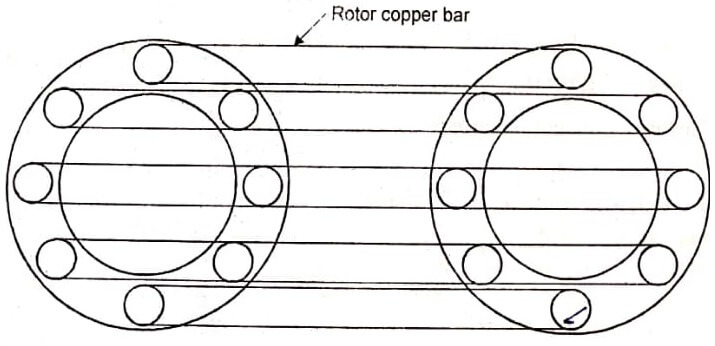
Figure shows a squirrel cage rotor. This is made up of a cylindrical laminated core with slots to carry the rotor conductors, The rotor conductors are heavy bars of copper or aluminum short circuited at both ends by end rings. Hence this rotor is also called a short circuited rotor. The entire rotor resistance is very small. External resistance cannot be connected in the rotor circuit. Such motors are extremely rugged in construction. Motors using such rotors are called squirrel cage induction motors. The majority of induction motors are cage rotors.
Slip ring or wound rotor
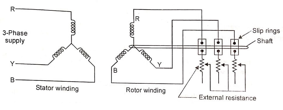
Figure shows a slip ring or wound rotor. In this type of rotor, rotor windings are similar to the stator winding. The rotor winding may be star or delta connected, distributed winding, wound for as many number of poles as the stator is wound for. The three phases are brought out and connected to slip rings mounted on the rotor shaft. Variable external resistance can be connected in the rotor, circuit, with the help of brushes and slip ring arrangements. By varying the external resistance in the rotor circuit, the motor speed and torque can be controlled. This motor is called slip ring induction motor or wound rotor induction motor.
| Read More Topics |
| Electrical machine design |
| Reactive power and voltage control |
| Energy efficiency of transformer |
