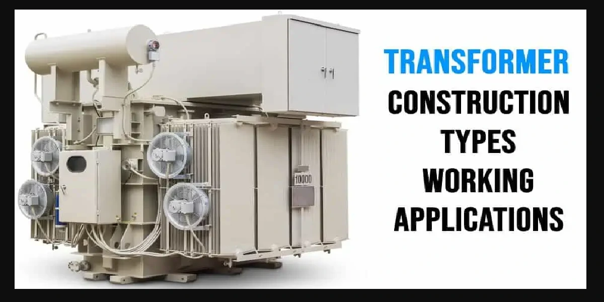
The generation of electric power is three-phase in nature and the generated voltage is 13.2kV, 22kV or higher. Transmission of power is carried out at high voltages like 132kV or 400kV. Before transmission, it is required to step-up the voltage and for this a thee phase step-up transformer is required. Similarly, at the distribution sub-station the voltage must be stepped down and it is necessary to reduce the voltage upto 6000V, 400V, 230V and so on.
Here a three phase stepdown transformer is required. Therefore it is economical to use three phase transformers for transmission and utilisation purposes.
Three phase transformer construction is similar to single phase transformer like shell or core type. It is shown in figure.
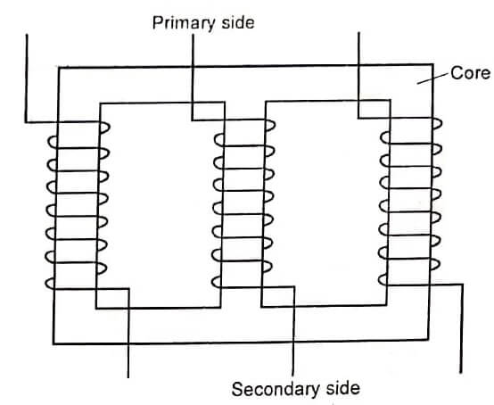
Three phase shell type transformer has three limbs. Here, we are using only I core. Around each limb, the primary and secondary windings are placed.
The operation of three phase transformer is similar to single phase transformer. Three phase supply (input voltage) is given to the primary winding. Due to this, three phase flux is produced in the primary winding.
This flux is linked with secondary winding. Depending upon the number of turns in the secondary, the secondary voltage will be stepped up or stepped down. The primary and secondary windings can be connected either in star or delta.
| Advantages of Three Phase Transformers |
| It occupies less space for same rating, compared to a bank of three single-phase transfomers. |
| It weight less |
| The cost is also low |
| Easy to handle |
| It can be transported very easily |
| The core is of a smaller size and hence less material is required. |
Three Phase Transformer Connections
The following are the most useful and commonly used transformer connections
- Star-star connection
- Delta-delta connection
- Star-delta connection
- Delta-star connection
Star – star connection
Figure shows star-star connection and vector group. This type of connection is most economical for small current rating, high voltage transformers because the phase voltage is 1/√3 times the line voltage.
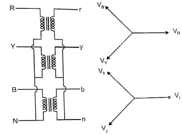
Here the number of turns per phase and quantity of insulation required is minimum. There is a phase shift of 30° between the phase voltages and line voltages on both primary and secondary where as line voltages in both primary and secondary are in phase with each other as shown in the phasor diagram.
The ratio of voltages on the primary and secondary sides is equal to the transformation ratio of each transformer. The star-star connection works well for balanced load. If the load is unbalanced, the neutral shifts.
To prevent this, star point of the primary is required to be connected to the star point of the generator. Let VL1 be the line voltage on the primary side. The phase voltage on the primary (Vph1) is given by,
![]()
If ‘a’ is the turns ratio, the phase voltage on the secondary is given by,

The star-star connection has the following advantages
- Less number of turns and less quantity of insulation is required because, Vph = VL /√3
- Since Iph , IL the current through the windings is high. The windings must. have a large cross-section and must be mechanically strong so that they can bear heavy load and short-circuit.
- There is no phase shift between the primary and secondary voltages.
- It is suitable for three phase and four wire system because of the presence of neutral point.
The star-star connection has the following disadvantages.
- The neutral point shifts due to unbalanced load and performance is not satisfactory.
- Inspite of connecting neutral point to earth, the third harmonic present in the alternator voltage may appear in secondary and cause distortion of secondary voltage.
Delta-delta Connection
Figure shows delta-delta connection and vector group. This arrangement is generally used in systems which carry large currents on low voltages and especially when continuity of service must be maintained even though one of the phases develops fault.
| Read More Topics |
| EMF equation of a transformer |
| Types of DC Generators |
| Energy efficiency of transformer |
