DC generators can be classified according to their methods of field excitation. There are two types of DC generators on the basis of excitation.
- Separately excited DC generators
- Self excited DC generators
Separately excited DC generators
If the field winding is excited by a separate DC supply, then the generator is called separately DC generator.
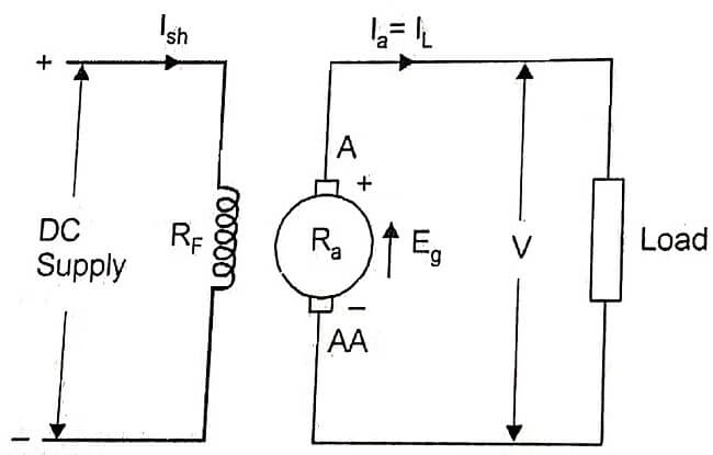
Figure shows the diagram of a separately excited generator. The field winding has large number of turns of thin wire.
From this diagram,
Armature current Ia = Load current IL
Ra = Resistance of the armature winding
Terminal voltage V = Eg – Ia Ra – Vbrush
Vbrush = voltage drop at the contacts of the brush.
Generally Vbrush is neglected because of very low value.
Generated emf Eg = V + Ia Ra – Vbrush
Electric power developed = Eg Ia
Power delivered to load = V Ia
Self-excited DC Generators
If in a D.C generator field winding is supplied from the armature of the generator itself, then it is called a self-excited D.C generator. Residual flux is present in the poles. When the armature is rotated, a small emf is produced in the armature winding because of residual flux.
This emf produces a small field current in the field winding. Then flux per pole increases. The increased flux increases the induced emf, which further increases the field current. Because of this cumulative process, generator produces its rated voltage. The self-excited generators can be classified depending upon how the field winding is connected to the armature. There are three types,
- Series generator
- Shunt generator
- Compound generator.
Series Generator

The field winding is connected in series with the armature. This type of D.C. generator is called D.C. series generator. Here, the armature current flows through the field winding as well as the load. The connection diagram for dc series generator is shown in figure.
The field winding las less number of turns of thick wire. It has low resistance. It is denoted by Rse. Here, armature, field and load are all in series. So they carry, the same current.
∴ Ia = Ise = IL
Generated emf Eg = V + Ia Ra + Ia Rse + Vbrush
where V = terminal voltage in volts
Ia Ra = voltage drop in the armature resistance.
Ia Rse = voltage drop in the series field winding resistance
Vbrush = brush drop
∴ Terminal voltage V = E – Ia Ra – Ia Rse – Vbrush
Power developed in the armature = Eg Ia
Power delivered to load = V Ia (or) V IL
Shunt Generator

In a d.c shunt generator, field winding is connected across the armature. The load is also connected across the armature. The shunt field winding has more number of turns of thin wire. It has high resistance. Therefore, a small amount of current flows through the field winding and large amount of current flows through the armature. Figure shows connections diagram of a D.C shunt generator.
Terminal voltage V = Eg – Ia Ra
Shunt field current Ish = V/Rsh
Armature current Ia = IL + Ish
Power developed by armature = Eg Ia
Power delivered to load = V IL
Compound Generator
The compound generator consists of both shunt field and series field windings. One winding is in series and other winding is in parallel with the armature. Depending upon the shunt field and series field connections, compound generator can be classified as
- Long shunt compound generator
- Short shunt compound generator
Long shunt compound generator
Figure shows connection diagram of a long shunt compound generator. Here, shunt field winding is connected across both series field and armature windings.

Ise = Ia = IL + Ish
Shunt field current Ish = V/Rsh
Generated emf E = V + Ia (Ra + Rse) + Vbrush
Terminal voltage V = Eg – Ia (Ra + Rse) – Vbrush
Power developed in armature = Eg Ia
Power delivered to load = V IL
Short Shunt Compound Generator
Figure shows short shunt compound generator. Here, shunt field winding is connected in parallel with the armature and this combination is connected in series with series field winding.
Series field current = Ise = IL
Load current = IL
Ia = Ish + Ise
Generated emf Eg = V + Ia Ra + Ise Rse + Vbrush

Voltage across shunt field winding = Ish Rsh
Ish Rsh = Eg – Ia Ra – Vbrush
= V + Ia Ra + Ise Rse + Vbrush – Ia Ra – Vbrush
= V + Ise Rse
Shunt field current Ish = V+ Ise Rse/Rsh
Terminal voltage V = Eg – Ia Ra – Ise Rse – Vbrush
Power developed in armature = Eg Ia
Power delivered to load = V IL
[sc_fs_faq html=”true” headline=”h2″ img=”” question=”What are the different types of D.C Generator?” img_alt=”” css_class=””] 1. Separately excited D.C Generator 2. Self excited D.C Generator a) Series generator b) Shunt generator c) Compound generator i) Long shunt compound ii) Short shunt compound [/sc_fs_faq]
| Read More Topics |
| DC Generator Principle |
| First law of thermodynamics |
| Second law of thermodynamics |
| Zeroth law of thermodynamics |
