When the excitation of a three phase synchronous motor taking constant power P from constant voltage supply main is varied, the power factor of the motor changes. The power drawn by a 3 phase synchronous motor is given by, P = √3 VI cosΦ where V is the line voltage, I is the armature current and cosΦ is the power factor. Since input power P and supply voltage V are constant, decrease in power factor causes increase in armature current and vice-versa.


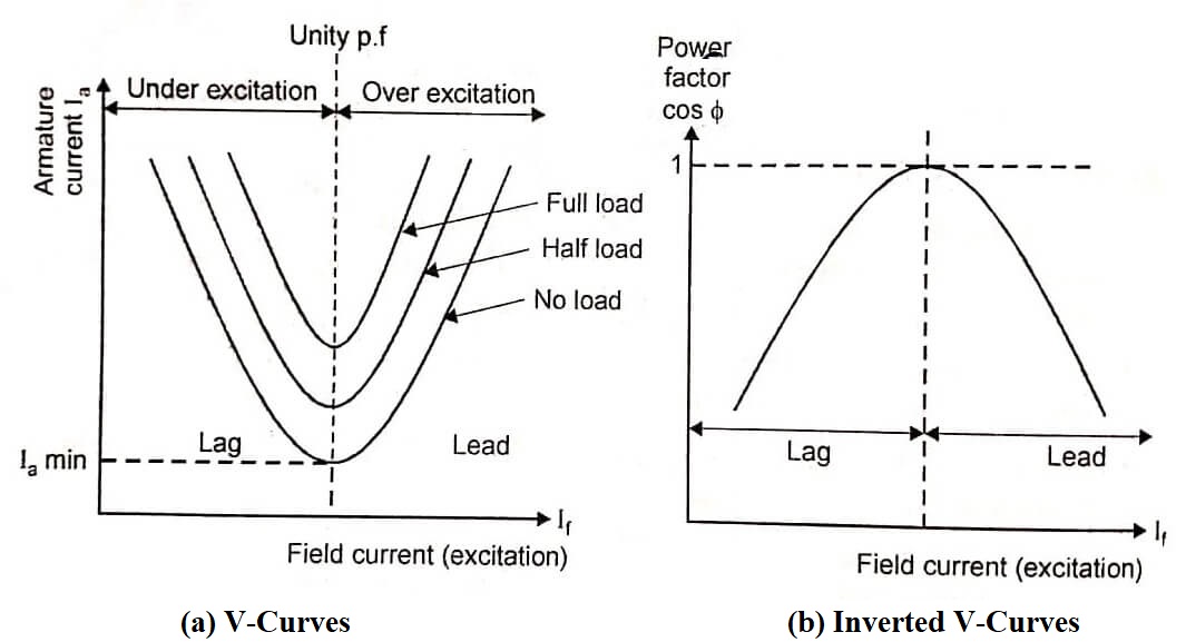
Hence variation in excitation or in field current causes the variation in armature current and curves drawn between armature current and field current for different power inputs are known as “V-curves” due to their shape similar to English letter V. The V-curves of a synchronous motor give relation between armature current and field current for different power inputs. It is shown in figure (a).
On the other hand, if the power factor (cosΦ) is plotted against the field current, the graph looks like an inverted V. The family of curves obtained by plotting power factor against field current for various conditions is known as inverted V curves of synchronous motor as shown in figure (b).
Figure shows the experimental set up to obtain V curves. Three-phase supply is given to stator. The two-wattmeter method is used to measure the input power. Ammeter reading gives the line current whereas voltmeter reading gives the line voltage. A rheostat is used in the field circuit to adjust the excitation to operate the motor under variable excitation.
- See More : Starting methods of synchronous motor
- See More : Torque of synchronous motor
- See More : Frequency of induced emf in rotor


