Networks in which electrical energy is fed in at one pair of terminals and taken out at a second pair of terminals are called two port networks. The network between the input port and the output port is a transmission network for which a known relationship exists between the input and output currents and voltages.
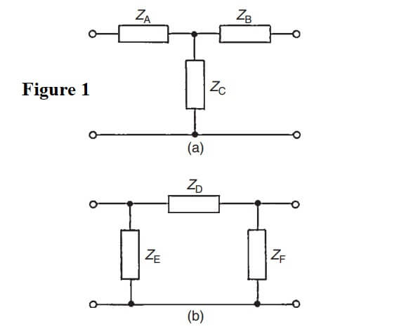
Figure 1(a) shows a T-network, which is termed symmetrical if ZA = ZB, and Fig. 1(b) shows a π-network which is symmetrical if ZE = ZF.
If ZA ≠ ZB, in Fig. 1(a) and ZE ≠ ZF in Fig. 1(b), the sections are termed asymmetrical. Both networks shown have one common terminal, which may be earthed, and are therefore said to be unbalanced.


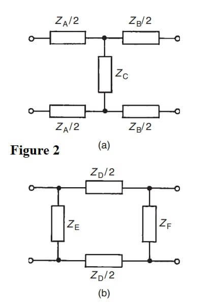
The balanced form of the T-network is shown in Fig. 2(a) and the balanced form of the π-network is shown in Fig. 2(b).
The input impedance of a network is the ratio of voltage to current at the input terminals. With a two port networks the input impedance often varies according to the load impedance across the output terminals. For any passive two-port network it is found that a particular value of load impedance can always be found which will produce an input impedance having the same value as the load impedance. This is called the iterative impedance for an asymmetrical network and its value depends on which pair of terminals is taken to be the input and which the output (there are thus two values of iterative impedance, one for each direction).
For a symmetrical network there is only one value for the iterative impedance and this is called the characteristic impedance Z0 of the symmetrical two-port network.
| Read More Topics |
| Maximum power transfer theorem |
| Bipolar junction transistors (BJT) |
| Conduction in semiconductor materials |
| Force on a current carrying conductor |


