Intro – Computer Control of Power System
Operation in plants with automated computer control of power system work mainly in a central control room. In olden plants, the controls for the equipment are not centralized and the switchboard operators control the flow of electricity from a central point, whereas, auxiliary equipment operation work throughout the plant, operating and monitoring valves, switches and gauges.
Electric power systems have grown in size and complexity. Their power generation, transmission and distribution methods and equipment have constantly improved in performance and reliability. The power industry in nuclear plant was among the first to use analog controls for turbine generators and introduced the use of on-line digital control computers. These advances were often needed because of the enormous growth in megawatt requirements of the power systems.
The satisfactory operating state is given by the following conditions : Frequency within normal operating range, bus voltage magnitude within specified range, current flows on all transmission lines within ratings, transformers and generators operate within their ratings, and no load shedding anywhere in the system.
ENERGY MANAGEMENT SYSTEM (EMS)
Energy management is the process of monitoring, coordinating and controlling the generation, transmission and distribution of electrical energy] It is performed at centres called ‘system control centres’, by a computer system called Energy Management System (EMS). Data acquisition and remote control is performed by the computer system called SCADA, which forms the front end of EMS. The EMS communicates with generating, transmission and distribution systems through SCADA systems.
Energy Management – Computer Control of Power System
Automatic generation control and economic dispatch minimize the production cost and transmission cost. Commit the number of units to be operated to minimize the cost and schedule hydro-thermal plants properly have come under energy management.
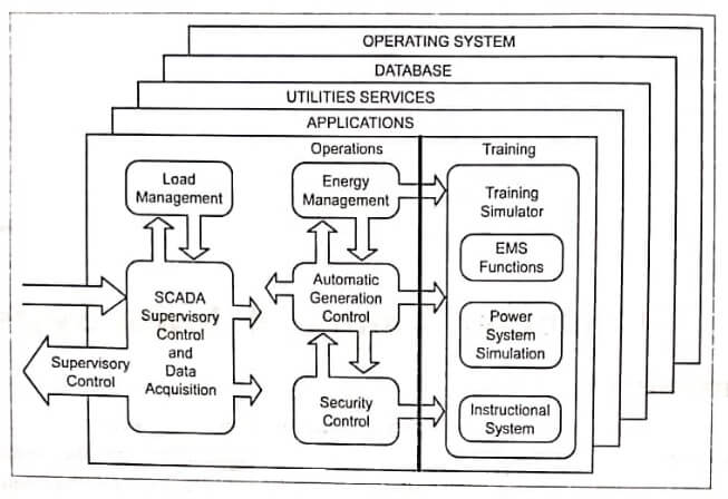
Energy management system consists of energy management, AGC, security control, SCADA, load management, as shown in image.
The functions of energy management systems are:
- System load forecasting – Hourly energy, 1 to 7 days.
- Unit commitment – 1 to 7 days.
- Fuel scheduling to plants.
- Hydro-thermal scheduling – upto 7 days.
- interchange evaluation – with neighbouring system.
- Transmission loss minimization.
- Security constrained dispatch.
- Maintenance scheduling.
- Production cost calculation.
Load Management – Carried out at Distribution Control Centre
Load Management
Remote terminal unit (RTU) installed at distribution substations, can provide status and measurements for distribution substation. RTU can monitor switches, interruptors, control voltage, customer meter reading.
The functions of load management are :
- Data acquisition.
- Monitoring, sectionalizing switches and create circuit configuration.
- Feeder switch control and preparing distribution map.
- Preparation of switching orders.
- Customer meter reading.
- Load management – control customer load.
- Fault location and circuit topology configuration.
- Service restoration.
- Power factor and voltage control.
- Implementation time dependent pricing.
- Circuit continuity analysis.
- To control customer load through appliance switching (Heater) and indirectly through voltage control
NERGY CONTROL CENTRE or SYSTEMS CONTROL CENTRE
When the power system increases in size the number of substations, transformers, switchgear and so on – their operation and interaction become more complex. So it becomes essential to monitor this information simultaneously for the total system which is called as energy control centre. A fundamental design feature of energy centre is that, it increases system reliability and economic feasibility. In other words, Energy Management (EM) is performed at control centre called system control centre.
Image shows the schematic diagram showing the information flow between various functions to be performed in an operations control centre computer system. The system gets information about the power system from remote terminal units (RTU) that encode measurement transducer outputs and opened closed status information into digital signals that are transmitted to the operations centre over communication circuits. The control centre can transmit control information such as raise / lower commands to the speed changer and in turn to the generators and open / close commands to circuit breakers (CBs). The information coming into the control centre is breaker / switch status indications and analog measurements. The analog measurements of generator outputs must be used directly by the Automatic Generation Control (AGC) program, whereas, all other data will be processed by the state estimator before being used by the other programs. Real time operations are in two aspects.
Three level control
- Turbine-governor to adjust generation to balance changing load-instantaneous control.
- AGC (called Load Frequency Control (LFC)) maintains frequency and net power interchange – action repeated at 2 – 6 sec. interval.
- Economic Dispatch Control (EDC) distributes the load among the units such that fuel cost is minimum – executed at 5 – 10 minutes intervals.

Primary voltage control
- Excitation controls regulate generator bus voltage.
- Transmission voltage control devices include SVC (Static VAR Controllers), shunt capacitors, transformer taps.
Automatic Generation Control (AGC)
- To hold frequency at or very close to a specified nominal value.
- To maintain the correct value of interchange power between control values.
- To maintain each unit’s generation at the most economic value.
In order to run the state estimator, we must know how the transmission lines are connected to the load and generator buses. This information is called as network topology. Since the breakers and switches in any substation can cause the network topology to change, a program must be provided that reads the telemetred breaker / switch status indicators and restructures model of the system. The network topology programs must have a complete description of each substation and how the transmission lines are attached to the substation equipment. Bus sections that are connected to the other bus sections through closed breakers or switches are designed as belonging to the the manner in which they same electrical bus. Thus, the number of electrical buses and are interconnected can be changed in the model to reflect breaker and switch status changes on the power system itself.
The electrical model of the transmission system is sent to the state estimation program together with the analog measurements. The output of the state estimator consists of all voltage magnitudes and phase angles, transmission line MW and MVAR flows and bus loads and generations calculated from the line flows. These quantities, together with the electrical
model, provide the basis for the economic dispatch program, contingency analysis program and generator corrective action program. Since the complete electrical model of the transmission system is available, we can directly calculate bus penalty factors, participation factors, optimal voltages.
Note Contingency Analysis : Many of the problems that occur on a power system can a cause serious trouble within such a quick time period that the operator cannot take action fast enough. This will cause cascading failures. Due to this aspect of system operation, modern operations, computers are equipped with contingency analysis programs that model possible
system’s troubles before they arise. These programs are based on a model of the power system and are used for study of outage events and alarm the operators of any potential overloads or out of the limit voltages. We are considering line outages and generator outages separately.
Energy Control Centre Functions
The practice of all communication links between equipment and the control centre could be interrupted and still, electric service is being maintained. The generating plant in the system remains synchronized to the transmission network and maintains its existing power output level even without signals received from control centre.
Monitoring
An energy control centre fulfills the function of coordinating their response of the system elements in both normal operation and emergency conditions. The burden of repetitious control in normal situations is delegated to the digital computer and selective monitoring is performed by human operators. The digital computer is used to process the incoming stream of data to detect abnormalities and then alarm the human operator via lights, buzzers and CRT presentations. Many lower level or less serious cases of exceeding normal limits are routinely handled by digital computer. A more serious abnormality detected by the digital computer may cause suspension of normal control functions. In emergencies such as loss of a major generator or excess power demands by a neighbouring utility on the tie lines, many alarms could be detected and the system could enter an emergency state.
SCADP Data Acquisition and Computer Control of Power System
Data acquisition provides operators and computer control of power system with status and measurement information needed to supervise overall operations. Security control analyses the consequences of faults to establish operating conditions. Data acquisition and remote control is performed by computer systems called supervisory control and data acquisition (SCADA) systems. A SCADA system consists of a master station and remote terminal unit (RTU). Master station communicates information to the RTU for observing and controlling plants. RTUs are installed at generating station or transmission substation or distribution substation. RTUs transmitting status of the device and measurements to master station and receive control commands from the master station, In a computer aided data acquisition scheme, the steady state reading can be acquired simultaneously from various instrument locations and can be saved for future analysis. The transients may be in the form of voltage or current fluctuations. In a real power system, the transient may result in the failure of components and it is sometimes difficult to trace the origin of disturbance. Using a Data Acquisition System, the transients can be reduced and analysed.


