A DC generator is one of the oldest but most trustworthy machines employed to transform mechanical energy into direct current electrical energy. Whether you are learning elementary electrical engineering or attempting to comprehend power systems, it is important that you understand how a DC generator works. So, let’s get into its basic concepts in the easiest possible manner.
What Is a DC Generator
A DC generator is a rotating electric machine which generates direct current electricity from mechanical energy. It is based on the law of electromagnetic induction and is routinely used in old power plants, battery charging, and low voltage systems.
Brief History and Background
The DC generation concept has its roots in the early 1800s through the work of Michael Faraday and Hippolyte Pixii as they designed the very first dynamo-type machines. AC generators became dominant in industrial applications, while DC generators remain applicable in certain fields.
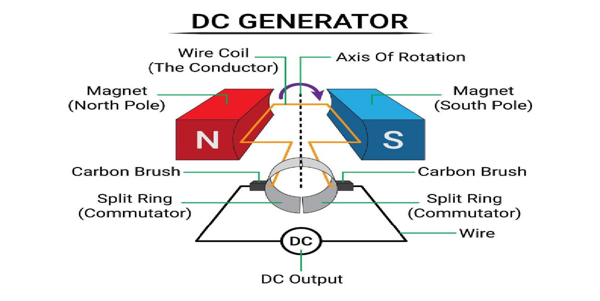
Working Principle of a DC Generator
Faraday’s Law of Electromagnetic Induction
The operation is based on Faraday’s Law, according to which if a conductor crosses a magnetic field, it induces an EMF (electromotive force) in the conductor.
How Energy Conversion Occurs
In a DC generator:
Rotates the armature using mechanical energy (turbine or engine).
Cuts the magnetic field lines within the generator.
Induces a current, which is subsequently recovered through commutators and brushes.
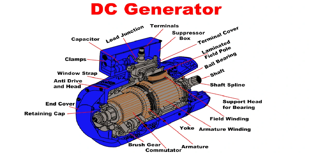
Construction of a DC Generator
Main Components of a DC Generator:
Yoke: Generator’s magnetic frame.
Armature Core: Rotating component where EMF is induced.
Field Windings: Supply magnetic field.
Commutator: Converts armature’s AC to DC output.
Brushes: Make contact with commutator and supply current to external circuit.
Types of DC Generators
Separately Excited DC Generator
An external power supply is used to energize the field windings.
Self Excited DC Generator
Field windings derive their power from the generator itself.
Series Wound Generator
Field winding in series with load.
Shunt Wound Generator
Field winding in parallel with the load.
Compound Wound Generator
Both series and shunt.
EMF Equation of a DC Generator
Formula:
E=P⋅Φ⋅Z⋅N60⋅AE = \frac{P \cdot \Phi \cdot Z \cdot N}{60 \cdot A}E=60\cdotAP⋅Φ⋅Z⋅N
Where:
E = EMF (V)
P = Number of poles
Φ = Flux per pole
Z = Total number of armature conductors
N = Speed in RPM
A = Number of parallel paths
Example Calculation
If P=4P = 4P=4, Φ=0.02Φ = 0.02Φ=0.02 Weber, Z=500Z = 500Z=500, N=1500N = 1500N=1500, A=2A = 2A=2:
E=4⋅0.02⋅500⋅150060⋅2=500VE = \frac{{4 \cdot 0.02 \cdot 500 \cdot 1500}}{{60 \cdot 2}} = 500VE=60⋅24⋅0.02⋅500⋅1500=500V
Characteristics of DC Generators
Open Circuit Characteristic (OCC): Field current vs. voltage generated.
Load Characteristic: Variation of terminal voltage with load.
Says Internal & External Characteristics: Internal behavior vs output delivered.
Applications of DC Generators
Battery charging
Welding operations
Excitation of synchronous motors
Railway traction systems
Advantages of DC Generators
Smooth and stable voltage
Easy to control speed
Suitable for low-voltage applications
Disadvantages of DC Generators
High maintenance
Brush and commutator wear
Not suited for high power output
Recent Developments & Future Scope
With the development of EVs and hybrid systems, compact DC generators are being rediscovered in niche applications such as:
Regenerative braking
Solar charging systems
Microgrids
Read also: EMF and internal resistance of a cell


