The gas turbine power plant has relatively low cost and can be quickly put into commission. Gas turbine installations require only a fraction of water used by their steam turbine counter parts. The size of gas turbine plants used varies from 10MW to 50MW and the thermal efficiency of about 22% to 25%. It is very much useful in peak load. The gas turbine plant requires less space only.
A gas turbine is similar to the steam turbine but hot gas is used to run the turbine. It is mainly used in the aircraft engines, electric power generation, marine propulsion etc. In this chapter, various types of gas turbines and its cycles will be discussed in detail. The practical limitations and modifications of the ideal cycle will be discussed.
Classification of Gas Turbines
- According to the cycle of operation
- Open cycle gas turbines
- Closed cycle gas turbines, and
- Semi closed cycle gas turbines
- According to the process
- Constant pressure gas turbines, and
- Constant volume gas turbines
- According to the use
- Industrial gas turbines, and
- Air craft gas turbines
- According to the type of load
- Peak load
- Stand by
- Base load
- According to the application
- Aircraft
- Marine
- Locomotive
- Transport
- According to the type of fuel
- Liquid
- Gas
- Solid
- According to the number of shafts
- Single shaft
- Multi shaft
Elements of a Gas Turbine Plant
The gas turbine power plant consists of
- Compressor
- Intercooler
- Regenerator
- Combustion chamber
- Gas turbine
- Reheating unit.
Compressor
In gas turbine power plant, the axial and centrifugal flow compressors are used. In most of the gas turbine power plants, two compressors are used. One is low pressure compressor and the other is high pressure compressor.
In the low pressure compressor, the atmospheric air is drawn into the compressor through the filter. The major part of the power developed by the turbine (about 66%) is used to run the compressor.
This low pressure air goes to the high pressure compressor through the intercooler. Then the high pressure air goes into the regenerator.
Intercooler
The intercooler is used to reduce the work of the compressor and it is placed between the high pressure and low pressure compressor. Intercoolers are generally used when the pressure ratio is very high. The energy required to compress the air is proportional to the air temperature at inlet. The cooling of compressed air in intercooler is generally done by water.
Regenerator
Regenerators are used to preheat the air which is entering into the combustion chamber to reduce the fuel consumption and to increase the efficiency. This is done by the heat of the hot exhaust gases coming out of the turbine.
Combustion chambers
Hot air from regenerator flows to the combustion chambers and the fuel like coal, natural gas or kerosene are injected into the combustion chamber. After the fuel injection, the combustion takes place. These high pressure, high temperature products of combustion are passed through the turbine.
Reheating unit
In this unit, the additional fuel is added to the exhaust gases coming out from the high pressure turbine, and the reheated combustion products goes into the low pressure turbine.
Gas turbine
Two types of gas turbines are used in gas turbine plant.
- High pressure turbine
- Low pressure turbine
The combustion products from the combustion chamber are first expanded in high pressure turbine and then it expands in the low pressure turbine. Due to the expansion in the gas turbine, the heat is converted into mechanical work. The gas turbine classification is based on the cycle of operation as follows.
Working Principle of a Gas Turbine Plant
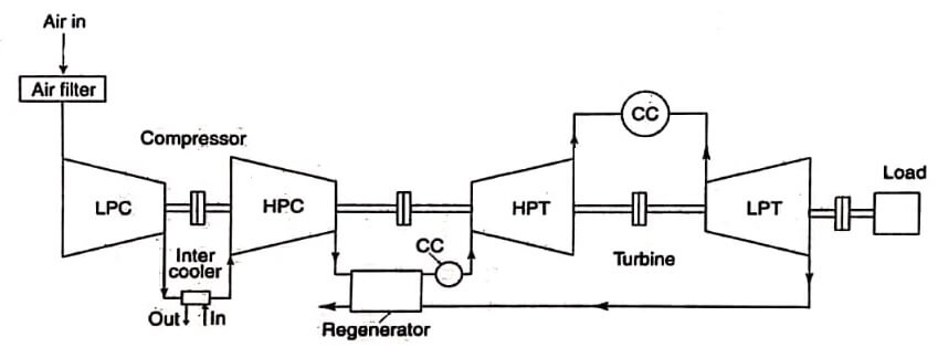
The working of gas turbine power plant is shown in image. The atmosphere air is drawn into the low pressure compressor through the air filter and it is compressed.
The compressed low pressure air goes into the high pressure compressor through the inter cooler. Here, the heat of the compressed air is removed. Then the high pressure compressed air goes into the combustion chamber through the regenerator. In the combustion chamber, the fuel is added to the compressed air and the combustion of fuel takes place.
The product of the combustion goes into the high pressure turbine. The exhaust of the high pressure turbine goes to. another combustion chamber and the additional fuel is added and it goes to the low pressure turbine.
After the expansion in the low pressure turbine, the exhaust is used to heat the high pressure air coming to the combustion chamber through the regenerator. After that, the exhaust goes to the atmosphere.
Fuels for Gas Turbine Plants
The advantages of increased gas turbine combustion temperatures increased efficiency, power and reduced fuel consumption are partially negated by increasing the cost of fuels normally used by gas turbines.
Residual liquid fuels, the residue left after the profitable light fractions have been extracted from the crude, have been used in gas turbines to some extend. The following properties are identified for residual liquid fuels.
- Viscous in nature.
- Tend to polymerise when overloaded
- Their high carbon content leads to excessive carbon deposits in the combustion chamber
- The contents of alkali metals, such as sodium, combine with sulphur to form sulphates that are corrosive
- They have other metals like vanadium with compounds that form during combustion also being corrosive
- They have a relatively high ash content that deposits mostly on the fixed blades, that reducing gas flow and power output.
The rate of corrosion increases with increasing gas temperature. Early turbines designed for residual fuel is operated at temperature below 900K to avoid the problem. Ash deposition is not a problem with intermittent operation because of successive expansions and contractions, but it is a series problem with steady operation.
The ideal fuel for the gas turbine units is natural gas from the view point of efficient energy conversion operation and pollution control. The fuel being clean would not foul the gas turbine blades and as such, the availability of the unit would be the highest. It is always advisable to use a gas turbine unit designed for multi-fuels (Gaseous as well as liquid fuels such as LPG, Kerosene, landfill gas, or oil). This would be useful for the operation of power station in case of non availability of one type of fuel due to some reasons.
The light distillates, such as light diesel oil, high speed diesel, naptha etc., would be the next preferred gas turbine fuels. These fuels can be used without treatment, if the contaminates are minimal. The gas turbine can also use heavy residual fuel oils as furnace oil and low sulphur heavy stock. The furnace oil has a viscosity of about 170 mm² /sec at 50°C with maximum sulphur content of 4.5% whereas low sulphur heavy stock is waxy in nature and has a viscosity of about 500 mm7/sec at 50°C with a maximum sulphur content of 1.5% and it has a pour point of 72°C. The low sulphur heavy stock has higher calorific value about 3.5% more compared to furnace oil. Also, it is cheaper by about 15% and has lower asphaltenses, ash and carbon residue. Both the furnace oil and low sulphur heavy stock could be used in the gas turbine, if pretreated properly to reduce contaminants within the acceptable limits.
Gas Turbine Material
The gas turbines are to be operated at high turbine inlet temperatures to achieve higher efficiencies and outputs. This also means higher pressure ratios because optimum pressure increases with increasing turbine inlet temperatures for both efficiency and power. The components that suffer most from a combination of high temperature; high stresses and chemical attack are those of the turbine first stage fixed blades nozzles and moving blades. They must be weldable and castable and must resist corrosion, oxidation, and thermal fatigue.
Heat resistance materials and precision casting are two recent advances, largely attributed to aircraft engine developments. Cobalt based alloys have been used for the first stage fixed blades which are subjected to the highest temperatures (but not the high stress) moving blades. These alloys are now being supplemented by vacuum cast nickel based alloys that are strengthened through solution and precipitation hardened heat treatment. For the moving blades, cobalt based alloys with high chromium content are now used.
Ceramic materials are also being developed, especially for the turbine inlet fixed blades. Developmental problems here are inherent brittleness which causes farication problems and raises uncertainties about the mechanical properties of ceramic materials.
| Read More Topics |
| Hydraulic and pneumatic systems |
| Air pollution and its control |
| Combined cycle nuclear power |


