A method of maintaining the speed of the turbine is constant irrespective of variation of the load on the turbine known as governing of turbine. The governors regulate the rate of flow to the turbine in such a way that the speed of the turbine is maintained constant as far as possible under varying load conditions.
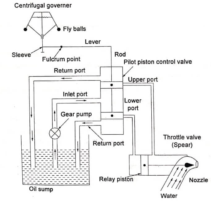
Centrifugal governors are generally employed with the modern turbines as shown in fig its components are as follows:
- Centrifugal governor
- Servomotor or relay cylinder
- Relay valve or control valve
- Gear pump
- Oil sump
- Spear or needle or throttle valve
Governing of Impulse Turbine
In impulse turbines, the discharge or flow rate is varied by adjusting the annular area of flow of the nozzle. The nozzle fitted at the end of the penstock is provided with a spear. The movement of the spear
is controlled by relay servomotor or relay cylinder. The relay piston is actuated by relay valve or control valve. There are two ports viz. upper port and lower port in the relay valve without any overlap. The relay valve is operated by lubricating oil supplied by a gear pump at 2 to 4bar. There is return port to drain the oil from this chamber. The relay valve controls the direction of flow of the oil in both sides of the servomotor.
The centrifugal governor is driven from the main shaft of the turbine by some mechanical arrangements. When the turbine is running at its normal speed, the position of relay piston, relay valve and fly balls of the centrifugal governor will be in the normal position as shown in fig. Both upper and lower ports in the relay valve are closed by the two wings of the control valve.
When the load on the turbine increases, the speed of the turbine will decrease. This decrease in speed of the turbine will decrease the speed of the centrifugal governor. Due to this, the fly balls will come down. This will also bring down the sleeve. This downward movement of the sleeve will raise the control valve rod.
Now, the control valve rod will open the upper port (Still keeping the lower port closed). Then, the oil will flow from the control valve to the right side of the servomotor piston. This will move the piston and spear towards the left. This movement of the spear will open more area of the nozzle and increase the rate of flow. Thus, the speed of the turbines is increased to normal.
When the load is decreased, the energy output of the turbine becomes in excess and the turbine shaft speed increases. Hence, the governor sleeve will lift. The upward movement of the sleeve will lower
the control valve rod thereby opening the lower port to oil flow to the servomotor and upper port to oil return. This will move the piston and spear towards the right which partially closes the area of the nozzle. As a result, the rate of flow will decrease and hence the speed of the turbine is reduced to normal.
Governing Of Francis Turbine
The working of servo motor and control is exactly same as the governing of Pelton wheel. The main difference in this governing is, the compensating device is introduced to prevent over travelling of the
governor.
When the relay piston or servo-motor moves right, the rod attached with relay piston at 3 in the bell crank 345 is rotated down as shown in fig. So, the arm 5 is pulled down by pulling pivot 1. Due to this,
fulcrum 2 is lowered. Therefore, the relay port ‘b’ is again closed to stop the motion. Thus, the over travelling of the piston is prevented.

If the relay piston continues this motion without compensating device, the relay piston would move beyond its required point. Due to this correct movement of the relay piston, the governor will move back to other side and keep the system steady.
Based on the speed of the turbine, the type of threads can be changed as either left hand thread or right hand threads. In addition to this, the length of the rod can be changed according to raise or lower the relay valve for changing the turbine.
For better governing of impulse turbines also, the same compensating device is suggested.
- See More : Pressure control valves
- See More : Directional control valves
- See More : Pelton wheel or Pelton turbine
- See More : Electroslag welding


