The analog waveforms are converted to digital signals by PCM, DM, ADM, DPCM etc. techniques. This digital data can be represented by different formats or waveforms. These waveforms are commonly known as digital data formats or their representation is called as line coding.
Digital symbols can amplitude modulate some carrier to generate amplitude modulated pulse train. Such signal may be represented as,
![]()
Here an is the modulating amplitude. It is the nth symbol in the message sequence. p(t) is the carrier signal. It’s pulses are modulated by an.
D is the maximum duration (time period) allowed for the carrier pulse. The unmodulated pulse p(t) is the rectangular pulse and it can take variable duty cycle. It can be represented as,
p(t) = 1 for t = 0
= 0 for t = ± D, ± 2D
x(t) is the baseband signal and continuous in time. To recover the original digital signal, we have to sample x(t) at some fixed intervals and check the signal in these intervals.
This checking is the detection of the transmitted symbols. From equation we see that when p(t) is zero, x(t) is zero. Therefore it is preferable to sample x(t) when p(t) is zero. That is at this time [P (t) = 0] no digital information is present/transmitted in the baseband signal. Therefore x(t) can be sampled periodically at t = nD where n = 0. ±1, ±2, … etc. p(t) is the rectangular pulse and can be written as,
p(t) = rect (t/τ)
Since the pulse to pulse interval is ‘D’, the width of the pulse τ should be less than or equal to D.
τ ≤ D
The signalling rate will be given as,
r = 1/D
If ‘D’ represents the duration of one bit, then D = Tb and signalling rate will be,
r = 1/Tb
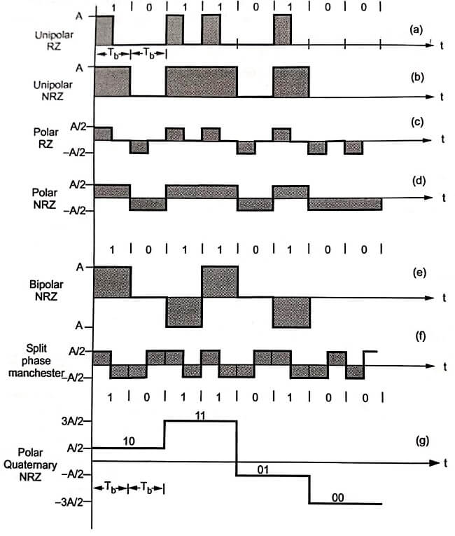
Various PAM formats are shown in line coding Fig. All the formats are shown for a binary message 10110100.

Unipolar RZ and NRZ
In unipolar format the waveform does have a single polarity. The waveform can have +5 or +12 volts when high. The waveform is simple on-off. In the unipolar RZ form, the waveform has zero value when symbol ‘0’ is transmitted and waveform has ‘A’ volts when ‘1’ is transmitted. In RZ form, the ‘A’ volts is present for Tb/2 period if symbol ‘1’ is transmitted and for remaining Tb/2 waveform returns to zero value, for unipolar RZ form, If symbol ‘1’ is transmitted,
If symbol ‘1’ is transmitted,
x(t) = A for 0 ≤ t < Tb/2 (Half interval)
= 0 for Tb / 2 ≤ t < Tb (Half interval)
And if symbol ‘0’ is transmitted,
x(t) = 0 for 0 ≤ t < Tb (Complete interval)
Thus in unipolar RZ format every pulse returns to a zero value. Fig (a) shows this signal format. A unipolar NRZ (not return to zero) format is shown in Fig (b). When symbol ‘1’ is to be transmitted, the signal has ‘A’ volts for full duration.
| Read More Topics |
| Concepts of sampling theorem |
| Adaptive delta modulation |
| Automatic frequency correction |


