INTRODUCTION TO DESIGN USING COMPENSATORS – Linear System Design
The control systems are designed to perform specific tasks in linear system design. The requirements of a control system are usually specified as performance specifications. The specifications are generally related to accuracy, relative stability and speed of response.
In time domain, the transient state performance specifications are given in terms of rise time, maximum overshoot, settling time and/or damping ratio. In frequency domain, the transient state performance specifications are given in terms of phase margin, gain margin, resonant peak and/or bandwidth. The steady state requirement are given in terms of error constants.
When performance specifications are given for single input, single output linear time invariant systems, then the system can be designed by using root locus or frequency response plots. To be more precise, when time domain specifications are given, root locus technique is employed in designing the system. If frequency domain specifications are given, frequency response plots like Bode plots are used in designing the system.
The first step in design is the adjustment of gain to meet the desired specifications. Practical systems, adjustment of gain alone will not be sufficient to meet the given specifications. In many cases, increasing the gain may result in poor stability or instability. In such cases, it is necessary to introduce additional devices or components in the system to alter the behaviour and to meet the desired specifications.
Such a redesign or addition of a suitable device is called compensation. A device inserted into the system for the purpose of satisfying the specifications is called compensator. The compensators basically introduce pole and/or zero in open loop transfer function to modify the performance of the system.
The design problem may be stated as follows:
When a set of specifications are given for a linear system design, then a suitable compensator should be designed so that the overall system will meet the given specification.
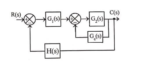
The compensation schemes used for feedback control system is either series compensation or parallel (feedback) compensation.
In series compensation, the compensator with transfer function, Gc(s) is placed in series with plant. In feedback compensation, the signal from some element is feedback to the input and a compensator with transfer function Gs(s) is placed in the resulting inner feedback path. The series and parallel compensation schemes respectively.
The choice between series compensation and parallel compensation depends on
- Nature of signals in the system.
- Power levels at various points.
- Components available.
- Designer’s experience.
- Economic considerations and so on.
The compensator may be electrical, mechanical, hydraulic, pneumatic or other type of device or network. Usually, an electric network or electronic device serves as compensator in many control systems. The different types of electrical or electronic compensators used are Lag compensator, Lead compensator and Lag lead compensator.

In control systems, compensation is required in the following situations in linear system design.
- When the system is absolutely unstable, then compensation is required to stabilize the system and also to meet the desired performance.
- When the system is stable, compensation is provided to obtain the desired performance.
The systems with type number 2 and above are usually absolutely unstable systems. Hence for systems with type number 2 and above, lead compensation is required, because the lead compensator increases the margin of stability.
In systems with type number 1 or 0, stability is achieved by adjusting the gain. In such cases any of three compensators-lag lead and lag-lead may be used to obtain the desired performance. The particular choice of compensator is based on the factors that are discussed in the following sections.
ROOT LOCUS APPROACH TO CONTROL SYSTEM DESIGN
- In design using root locus, the desired behaviour is specified in terms of transient response specifications and steady-state error requirement. The steady-state error is usually specified in terms of error constants for standard inputs, while the transient response requirement is specified in terms of peak overshoot, settling time, rise time, etc., for a step input. The transient response specification can be translated into desired locations for a pair of dominant closed loop poles.
- In order to meet the desired specifications, the root loci are reshaped so that they pass through the points where the dominant closed loop poles are located. The root loci are reshaped by introducing a compensator. The compensator will add a pole and/or a zero in the open loop transfer function of the linear system design.
- The addition of a pole to the open-loop transfer function has the effect of pulling the root locus to the right, which reduce the relative stability of the system and increase the settling time. The addition of a zero to the open-loop transfer function has the effect of pulling the root locus to the left which make the system more stable and reduce the settling time.
| Read More Topics |
| Memory interfacing and I/O interfacing |
| Microprocessor controlled temperature system |
| Serial communication programming and interrupt |