Flywheels : Mechanical energy may be stored in the form of kinetic or potential energy. A flywheel, in essence, is a mechanical battery simply mass rotating about an axis. Although the use of the flywheel as a kinetic energy storage device is well known, it has not, until recently, been considered
practical to build flywheels that could store energy for several hours or days. They take an electrical input to accelerate the rotor up to speed by using the built-in motor, and return the electrical energy by using this same motor as a generator. Steel flywheels have been used to power certain types of vehicles, such as buses and trucks, for very short runs, but the energy storage periods have at the best been for a few minutes.
The basic problems of flywheels are as follows. First, the stress in any rotating structure is proportional to the first power of the diameter and second power of the angular velocity. With steel structures, the limiting stresses are exceeded before any significant amount of usable energy can be stored.
Second, even if the flywheel could store significant energy, it would soon be dissipated by bearing friction and windage losses. It has been pointed out by Post and Rabenhorst that one or two orders of magnitude improvement over conventional flywheel technology could be achieved by
- Using fiberglass resins and polymer materials, which have a much higher strength weight ratio than steel.
- Running the flywheel in a vacuum.
- Using air or magnetic suspension bearing technology developed in recent years.
If the projections of Post and Rabenhorst are supported by experimental evidence, it appears that flywheel could become practical for storing significant amount of energy efficiently for several hours. This could make flywheel practical for electrical peaking and short run vehicular transportation.
Flywheels involve the storage of kinetic energy in a rotating object. The stored energy is proportional to the object’s moment of inertia times the square of its angular velocity. In order to optimize the energy to mass ratio, the flywheel needs to spin at the maximum possible speed. For a flat disk, the moment of inertia is proportional to its mass times the square of its radius. Therefore, the energy stored is proportional to its mass and the square of angular velocity.
Rapidly rotating objects are subject to centrifugal forces that can rip them apart. Thus, while dense material can store more energy, it is also subject to higher centrifugal force and thus fails at lower rotational speeds than low density materials. Therefore, tensile strength is more important than the density of the material. Two approaches to flywheel energy storage are generally pursued.
The commonly used approach is to use a heavy material, like steel, and operate at a moderate speed. The other approach, the so called advanced flywheel, uses lighter high strength materials like glass or carbon fibers and operates at high speed. Recent advances in composite materials technology may allow nearly an order of magnitude advantage in specific strength of composite when compared to even the best engineering metals. The result of this continuous research in composite has been a flywheel that operates at rotational speed in excess of 100,000 rpm with tip speeds in excess of 1000 m/s.
Flywheels have smoothed our energy sources in such historic applications as the potter’s wheel, the grain mill, and the water wheel. Today, its best use is in engines of various types. For large scale electric storage, economics would dictate the use of lighter weight high speed (30,000 r/min) wheels operating in a vacuum and using magnetic bearings to reduce friction. Under these conditions, energy efficiencies of about 80% are achievable. Since the speed of the wheel will change as energy is added or withdrawn, the motor generator will have to accommodate variable speeds.
Several approaches to variable speed generation have been investigated for wind application, although today’s wind machines use fixed speed generators. Conservation measures have encouraged the use of variable speed motors, and several manufactures now have this technology available in large sizes, for such applications as thermal power plant fans and pumps.
The flywheel itself is an expensive way to store energy, with costs probably twice that of the lead acid battery. However, it has several advantages over chemical energy storage, like energy density and better capability to exchange energy.
However, for application such as utility system regulation, where there are high-power and low energy requirements, flywheels would be suitable if integrity and reliability can be demonstrated. The ideal use for today’s flywheels is still to absorb and dissipate mechanical energy to smooth the operation of rotating machinery.
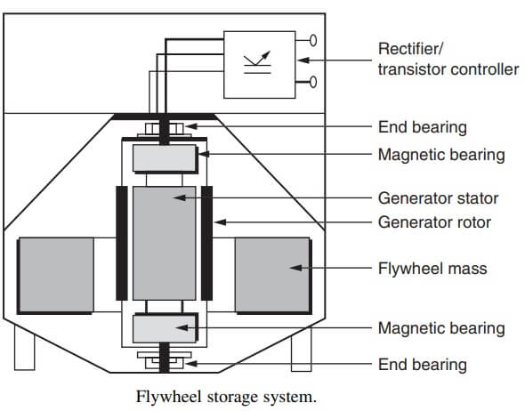
The ultrahigh rotational speed required to store significant kinetic energy in these systems virtually rules out the use of conventional mechanical bearings. Instead most systems run on magnetic bearings. These relatively recent innovations use magnetic forces to leviate a rotor, eliminating the frictional losses inherent in rolling element and fluid film bearing. Unfortunately, aerodynamic drag losses force most high speed flywheels to operate in a partial vacuum. A modern high-speed flywheel system is shown in fig.
Pumped Storages : Mechanical energy may be stored in the form of potential energy by pumping water to a reservoir at a higher level and allowing it to flow down to a lower reservoir whenever the energy is required. In this pump-back system, the kinetic energy of the flowing water is usually converted to electrical energy, although it can be used directly as mechanical energy.
The energy can be extracted from the hydro power plant depending on both the volume of the water available and the head of the water that can be exploited. The pump storage will provide the most efficient and cheapest operation when it can be provided a high head between the two reservoirs. This will allow greatest amount of energy to be stored in the smallest volume of water resulting in a smaller pump and turbine, reducing capital costs.
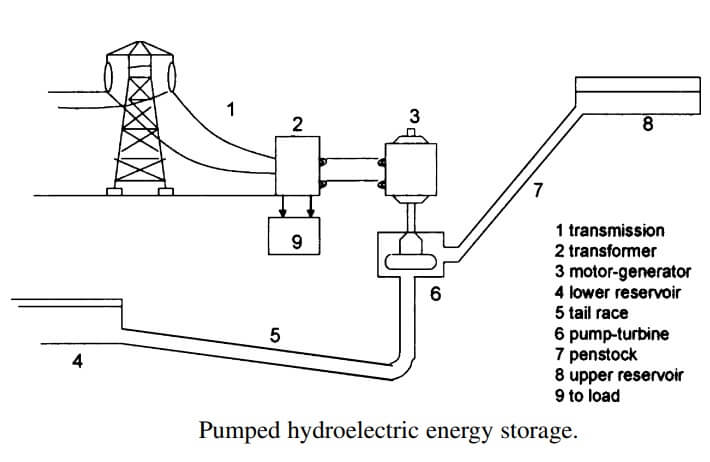
Pumped hydro storage usually comprises the upper reservoir, waterways, a pump, a turbine, a motor, a generator, and lower reservoir as shown schematically in the fig.
A difficulty of the pump-back storage system is that relatively large reservoirs are required. Most pump-back systems are built where there is a large natural basin for an upper reservoir located near an existing lake or river, the latter serving as the lower reservoir. With current technology in pump back systems, generally about two thirds of the energy is available for utilization after storage.
Hydraulic turbines have a maximum efficiency of around 95% and pumps are less efficient operating around 90%. Therefore, pump storage plants will have maximum efficiency of around 85%.
Pumped hydro or pumped storage, as it is often called, has been used in electric utility systems for over 50 years. Electricity is used to operate a motor generator combination to pump water to an elevated reservoir. When energy is required, water is allowed to flow down to a lower reservoir through a turbine generator combination, much like the turbine generators in conventional hydroelectric plants. The energy stored is proportional to the head (height differential between the upper and lower reservoir) times the stored volume of water. For head of 1200 ft, 36 ft of water is required for generation of 1 kWh. For a head of 120 ft, 360 ft of water is required to generate 1 kWh.
In areas where topographic or ecological considerations rule out pumped hydro plants, utilities now may choose to go underground. A modification of pumped hydro, underground pumped hydro (UPH) would have its lower reservoir located about a mile below the earth’s surface in a competent hard-rock cavern. A UPH plant therefore can be sited in flat terrain and should have only a minimal effect on the surrounding environment. The most significant drawback of UPH is that the plants must be in huge sizes (2,000 MW/20,000 kWh) to be economically attractive.
Both pumped hydro and UPH, like conventional hydro, have very fast response characteristics (emergency full power capability is 10 s) and very high efficiencies (72% to 75%). These factors, along with low capital costs, have led to the construction and operation of 18,000 MW of pumped hydro in the United States. Another 16,000 MW is planned or under construction. Pumped hydro typically will be the storage alternative of choice for electric utilities having favorable topography. Main barriers for the future growth in pumped hydro capacity are the availability of suitable sites and large environmental impact of these schemes.
Compressed Air : Another method for storing mechanical energy is through compressed air. Two basic methods are of interest: direct compression and isothermal compression. Direct compression, to be practical, requires the availability of natural or man-made underground caverns, which can be sealed off and pressurized to hydrostatic pressure or below. Utilization of the stored energy requires the availability of low pressure turbines or piston engines similar to the old style steam engines.
Generally, such systems provide a relatively low overall efficiency. About one-third of initial energy can finally be utilized. This figure can be improved considerably when compressed air system is combined with gas turbine cycles or with refrigeration cycles, because the energy required to compress the turbine inlet air need not be charged against turbine fuel efficiency if the air is already compressed.
Of increasing interest is isothermal hydraulic compression. In this process (which is at least 3,000 years old), a vertical tube is placed in front of a dam which is creating a head of water (typically 5 to 10 m). Water flowing into the inlet entraps air bubbles, which are carried with water. The water then passes through the bottom of a sealed tank or cavern, where the air bubbles rise. Ultimately, the air in the tank or cavern is compressed to a pressure slightly under the hydraulic head of the vertical (venturi) tube.
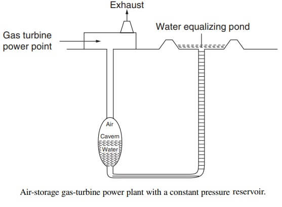
That compressed air can then be used in a simple turbine or other suitable expander to obtain usable mechanical energy. Such isothermal hydraulic compressors were used from ancient times until the later part of the nineteenth century, when they were gradually replaced by electrical, steam, or internal combustion devices. Because the compression is isothermal, the apparent efficiency of such systems can be very high, and with the rising cost of fuel, interest in this storage system is rapidly rising. A typical air storage gas turbine power plant with a constant pressure reservoir is shown in fig.
CAES involves the compression of air into an underground cavern or reservoir (excavated rock, solution mined salt, or aquifer) where it is stored. Favorable geologies exist in about 75% of the United States. Geologic considerations generally dedicate that most of the heat of compression be removed (and used or stored, if possible) before the air is stored underground. During generation, the air is expanded through a turbine to drive a generator. Economics dictates that heat be added to the air from a thermal store or through combustion of fuel prior to the expansion generation phase.
CAES technology recently has become commercialized for electric utility application. The commercial units incorporate modified combustion turbines wherein the compressor and expander are physically separated by clutches and motor generator. For the expansion-generation phase, the technology uses oils or gas, although other fuels can be used.
When a heat exchanger is incorporated to use exhaust heat to raise the temperature of the pressurized air, the overall energy balance involves approximately 4,000 Btu of oil or gas (during the generation phase) and 0.775 kWh of electricity (for the compression step) to produce 1 kWh of plant output.
Typical energy storage efficiencies cannot be calculated because a mixture of fuels is used. However, overall energy use is about 11,500 Btu/kWh, assuming the electricity for compression was generated at 10,000 Btu/kWh. A storage device using only electricity would have an efficiency of 87% to achieve an overall fuel use of 11,500 Btu/kWh, again assuming charging electricity is generated at 10,000 Btu/kWh. CAES system can be used on very large scales.
Unlike other systems considered, large-scale CAES is ready to be used with entire power plants. Apart from the hydro pump, no other storage method has a storage capacity as high as CAES. Typical capacities for a CAES system are around 50 to 300 MW. The storage period is also the longest due to the fact that its losses are very small. A CAES system can be used to store energy for more than a year. The main drawback of CAES is probably the geological structured reliance.
| Read More Topics |
| Electrochemical Energy Storage |
| Thermal energy based process |
| High energy rate forming process |
