Methods of Voltage Control
Methods Voltage control level is accomplished by controlling the generation, absorption and reactive power flow at all levels in the system.
The following are the methods of voltage control.
- By excitation control.
- By static shunt capacitors.
- By static series capacitors.
- By static shunt reactors.
- By synchronous condensers.
Other methods for voltage control
- Tap-changing transformer.
- Booster transformer.
- Regulating transformer.
- Static VAR compensators.
Shunt Capacitors
Shunt capacitor banks are used to supply reactive power at both transmission and distribution levels; along lines or sub-stations and loads. Capacitors are either directly connected a to a busbar or to the tertiary winding of a main transformer. They may be switched on and off depending on the changes in load demand. When they are in parallel with a load having a lagging power factor, the capacitors supply reactive power.
Shunt capacitors are extensively used in industrial and utility systems at all voltage levels. By developing higher power density, lower cost improved capacitors and an increase in energy density by a factor of 100 is possible. These present a constant impedance type of load, and the capacitive power output varies with the square of voltage.
![]()
where,
Kvar ,v1 is output at voltage V1, and Kvar, v2 is output at voltage v2
As the voltage reduces, SO does the reactive power, output, when it is required the most. This is called the destabilizing effect of power capacitors. Capacitors can be switched in certain discrete steps and do not provide a stepless control. A two-step sequential reactive power switching control is used to maintain, voltage within a certain band. As the reactive power demand increases, voltage falls.
Rise in Voltage Due to Shunt Capacitance
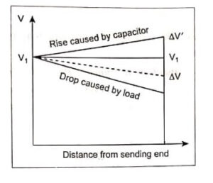
The equivalent circuit of a short transmission line with static shunt capacitor is as shown in Image.
Voltage drop without the shunt capacitor
ΔV = P2R+Q2X/V
Voltage drop with shunt capacitor is,.
ΔV = P2R+(Q2-Qc)X/V
Capacitor raises the voltage, Voltage profile of a radial feeder having a capacitor is depicted in image.
Methods of Voltage Control – Advantages
- These are less costly.
- Flexibility of installation and operation
- Power factor improvement.
- Efficiency of transmission and distribution of power is high.
- Single or multiple substation. banks in industrial distribution at low and medium voltage
- Essential elements of SVC and FACTS controllers and HVDC transmission.
- Reactive power compensation.
Disadvantages
- They cannot be overloaded.
- The reactive power supplied by static capacitors tends to decrease in case of voltage dip on the bus because KVAR ∞ V2.
Problems Associated with Shunt Capacitors
> Switching inrush currents at higher frequencies and switching over voltages.
> Harmonic resonance problems.
>Limited overvoltage withstand capability.
> Limitations of harmonic current loadings.
> Possibility of self-excitation of motors when improperly applied as power factor improvement capacitors switched with motors.
- See More : Series capacitor voltage
- See More : Analog link in optical
- See More : Penalty power in optical communication


