Microprocessor – controlled temperature system is used to
- Read the temperature in a room
- Display the temperature at LCD/LED panel
- Turn-on a fan if the temperature is above the limit.
- Turn-on a heater if the temperature is below the limit.
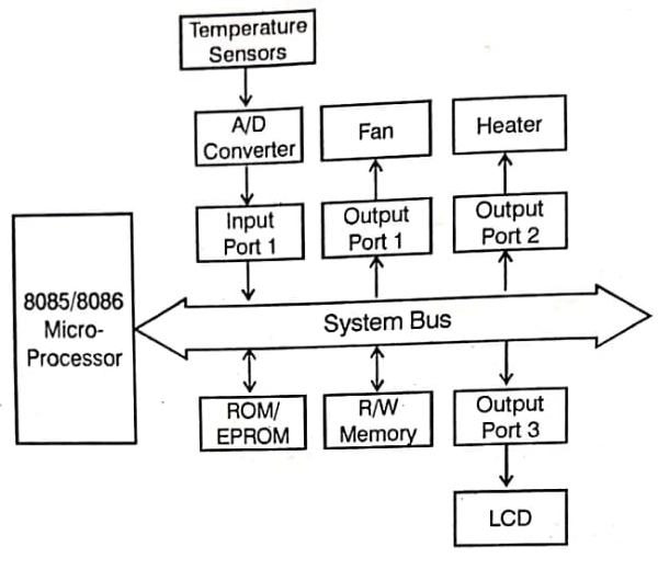
This system has a temperature sensor as an input device to sense room temperature and three output devices: a fan, a heater and display panel.

Microprocessor
Fig shows an 8085/8086 processor with a system bus; The processor will read the binary instructions from memory and execute those instructions continuously. It will read the temperature, display it at the LCD display panel, and turn on/off the fan and the heater based on the temperature.
Memory
The system includes two types of memory ROM and R/W memory. ROM (read-only memory) will be used to store the program, called the monitor program, that is responsible for providing the necessary instructions to the processor to monitor the system. This will be a permanent program stored in ROM and will not be altered. The R/W (read-write) memory is needed for temporary storage of data.
Input
In this system, we need a device that can translate temperature (measurement of heat) into an equivalent electrical signal; a device that translates one form of energy into another form is called a transducer. A temperature sensor is a three terminal semiconductor electronic device (a chip) that generates a voltage signal that is proportional to the temperature. However, this is an analog signal and our processor is capable of handling only binary bits. Therefore, this signal must be converted into digital bits. The analog to digital converter (ADC) performs that function.
The ADC is an electronic semiconductor chip that converts an input analog signal into the equivalent eight binary output signals. In microprocessor based systems, devices that provide binary inputs (data) are connected to the processor using devices such as buffers called input ports. In this system, this ADC is an input port, and it will be assigned a binary number called an address. The microprocessor reads this digital signal from the input port.
Output
Fig shows three output devices: fan, heater and liquid crystal display (LCD). These devices are connected to the processor using latches called output ports.
Fan is an output device, identified as Port 1 , that is turned on by the processor when the temperature reaches a set higher limit.
Heater is also an output device, identified as Port 2, that is turned on by the processor when the temperature reaches a set lower limit.
LCD is made of crystal material placed between two plates in the form of a dot matrix or segments. It can display letters, decimal digits, or graphic characters. The LCD will be used to display temperatures.
Program
The program that runs the system is called a monitor program or system software. Generally, the entire program is divided into subtasks and written as independent modules, and it is stored in ROM (or EPROM). When the system is reset, the microprocessor reads the binary command (instruction) from the first memory location of ROM and continues in sequence to execute the program.
| Read More Topics |
| Data handling instruction in PLC |
| Communication between 8086 and 8089 |
| Memory Interfacing and I/O Interfacing |


