End effectors require power to operate. They also require control signals to regulate their operation. The principal methods of transmitting power and control signal to the end effector are:
- Pneumatic
- Electric
- Hydraulic
- Mechanical
The method of providing the power to the end effector must be compatible with the capabilities of the robot system.
For example, it makes sense to use a pneumatically operated gripper if the robot has incorporated into its arm design the facility to transmit air pressure to the end effector.
The control signals to regulate the end effector are often provided simply by controlling the transmission of the actuating power.
The operation of a pneumatic gripper is generally accomplished in this manner. Air pressure is supplied to either open the gripper or to dose it.
In some applications, greater control is required to operate the end effector. For example, the gripper might possess a range of open/close positions and there is the need to exercise control over these positions.
In more complicated cases, feedback signals from sensors in the end effector are required to operate the device.
These feedback signals might indicate how much force is being applied to the object held in the gripper, or they might show whether an arc-welding operation was following the seam properly.
In the paragraphs below, we will explore the four methods of power and signal transmission to the end effector.
Pneumatic power using shop air pressure is one of the most common methods of operating mechanical grippers. Actuation of the gripper is controlled by regulating the incoming air pressure. A piston device is typically used to actuate the gripper.
Two air lines feed into opposite ends of the piston, one to open the gripper and the other to close it.
This arrangement can be accomplished with a single shop air line by providing a pneumatic valve to switch the air pressure from one line to the other. A schematic diagram of a piston is illustrated in fig.
When air pressure enters the left portion of the piston chamber the piston ram is extended, and when air is forced into the opposite end of the chamber, the piston ram is retracted.
The force supplied by the piston on the extension stroke is equal to the air pressure multiplied by the area of the piston diameter.
Because of the diameter of the piston ram, the force supplied by the piston on the retraction stroke is less than on the extension stroke.
These piston forces can be calculated as follows:
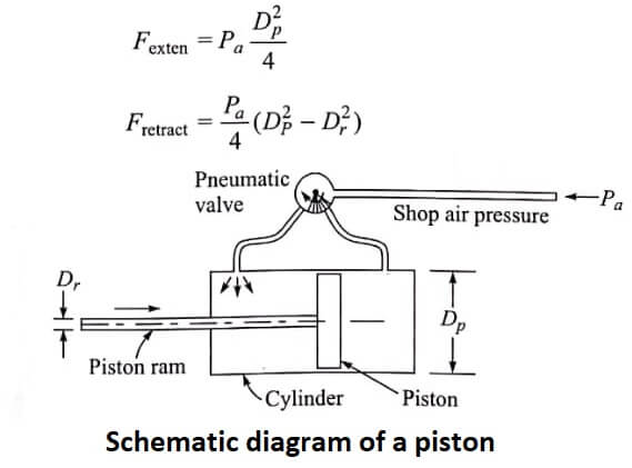
where Fexten = the piston force on the extension stroke, lb
Fexten = the piston force on the retraction stroke, lb
Dp = the piston diameter, in.
Dr = the ram diameter, in.
Pa = air pressure, lb/in².
we will illustrate the kind of engineering analysis required to design a pneumatic piston for a mechanical gripper.
| Read More Topics |
| Conductivity of semiconductor |
| Electrostatic sensors and actuators |
| Permanent Magnet Moving Coil Instrument |
| Primary source of electric power |
