The speed of an induction motor can be controlled by two major methods. They are:
- Stator side control
- Rotor side control
The first method is applicable for both squirrel-cage and wound-rotor motors. The second method can be used only for wound-rotor motors.
Stator side control means, we have to vary the stator side parameters, supply voltage, frequency, no. of poles etc. Rotor side control means, we have to vary the rotor side parameters, rotor resistance.
Types of speed control
Types of stator side control
- stator voltage control
- Stator frequency control
- V/f control
- Pole changing method
Types of rotor side control
- Adding external resistance in the rotor circuit.
- Cascade control.
- Slip power recovery scheme
Change in Stator voltage
The speed of the induction motor can be controlled by varying the stator voltage. This method of speed control is known as stator voltage control. Here, the supply, frequency is constant. The stator voltage can be controlled by two methods.
- Using auto transformer.
- Primary resistors connected in series with stator winding.
Using auto transformers :

The speed of the induction motor can be controlled by using auto transformer. It is shown in figure. The input to the auto transformer is a fixed ac voltage. By varying the auto transformer, we can get variable ac output voltage without change in supply frequency. The variable voltage is fed to the induction motor. Then the induction motor speed also changes.
Primary resistors connected in series with stator winding :
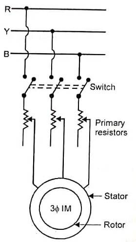
The primary resistors are connected in series with stator windings as shown in figure.
By varying the primary resistance, the voltage drop across the motor terminals is reduced. That is, reduced voltage is fed to the motor. Then the motor speed can be reduced. It is one method of conventional speed control of induction motor. The control method is very simple. The main disadvantage is that more power loss occurs in the primary resistors.
The torque is, proportional to the square of its stator voltage. T α V² By varying the voltage the torque also changes.
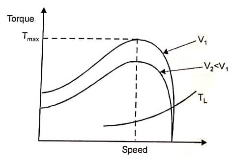
Figure shows the speed torque characteristics of induction motor under stator voltage control. Here the slip at the maximum torque remains unchanged since it is not a function of voltage.
By varying the stator voltage, the maximum torque and starting torque also change. For a low slip motor, the speed range is very narrow. So this method is not used for wide range of speed control and constant torque load. This is applicable where load requiring low starting torque and a narrow speed range at relatively low slip are required.
Change in Stator frequency
The stator frequency control is one of the methods of speed control for a 3 phase induction motors. Here, we can vary the input frequency of the motor.
Under steady state condition, the induction motor operates in the small-slip region; where the speed of the induction motor is always close to the synchronous speed of the rotating flux. The synchronous speed of the induction motor is given by N2 = 120f/P.
Where, f = frequency of the supply voltage, P = Number of poles.
In this equation, synchronous speed of the motor is directly proportional to the frequency of the supply voltage. When the supply frequency changes, the motor speed also changes. It is possible only, by controlling the speed of the prime movers of the’ generators. This method is rarely used. This is shown in figure.

The emf V induced in the stator winding of the induction motor is given by V = 2πf T1 Φ Kw
Where, Φ = Flux / pole
Kw = winding factor
f = Frequency of stator supply
T1 = No. of turns in the stator winding.
Here we consider two cases.
- Low frequency operation at constant voltage.
- High frequency operation at constant voltage.
Low frequency operation at constant voltage :
By decreasing the supply frequency at constant voltage V the value of air gap flux increases and the induction motor magnetic circuit gets saturated. Consider the emf equation.
V = Constant
f = Decrease
Φ = Increases
Due to this low frequency operation, the following effects take place.
- The reactance will be low leading to high motor currents.
- More losses
- Very low efficiency
High frequency operation at constant voltage :
With the constant input voltage, if the stator frequency is increased, the motor speed also increases. Due to increase in frequency, flux and torque are reduced.
V = Constant
f = Increase
Φ = Decreases
By increasing the supply frequency of the motor, the following effects will follow:
- The no-load speed increases
- The maximum torque decreases
- Starting torque reduces
This type of frequency control is not normally used because of the above disadvantages.
| Read More Topics |
| Three phase transformer |
| DC Generator principle |
| Electrical braking of DC motor |
[sc_fs_faq html=”true” headline=”h2″ img=”” question=”What is meant by stator voltage control?” img_alt=”” css_class=””] The speed of an induction motor can be controlled by varying the stator voltage. This method of speed control is known as stator voltage control. Here, the supply frequency is constant. The stator voltage can be controlled by two methods. [/sc_fs_faq]
