When 3- Φ Induction motor is switched on at normal supply voltage, heavy current “ill flow through the motor because at the time of starting, there is no back emf. An induction motor, when directly switched on, takes five to seven times its full load current and it develops only 1.5 to 2.5 times full load torque. This initial inrush of excessive current is objectionable because it will produce large line voltage drop. This will affect the operation of other electrical equipments connected to the same line.
Types of starters
- DOL starter
- Primary resistance starter
- Autotransformer starter
- Star delta starter
- Rotor resistance starter
Direct on Line Starter (DOL)
A motor of small capacity and which gathers normal speed quickly can be started with this starter. A small capacity motor (below 2kW) draws only small amount of current. This may not cause much voltage drop in the supply line.
Figure shows a 3-Φ induction motor with a DOL starter. M1, M2,M3 are main contactors normally open (NO) type making and breaking the motor line current. These contactors are operated by a relay coil. S2,S3 and S4 are normally closed (NC) type and are connected in series with relay coil. Over load relay coil (OLRC) is connected in series with motor line supply.
Operation
When TPST switch is closed, the Under Voltage Relay Coil (UVRC) is energized and it will operate the main contactors to close. Hence the full voltage is given to the motor and it runs. Closing of contactor A retains the supply to the UVRC.
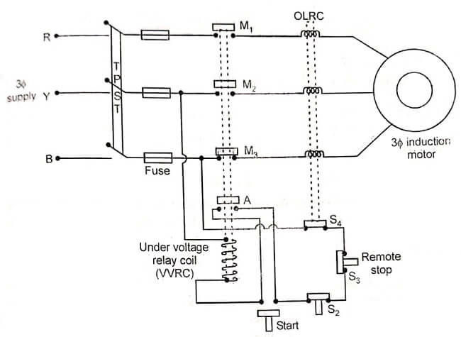
Contactor S2 is used to disconnect the supply from the motor by manually pressing it. Remote operation of the same can be achieved with the help of contactor S3.
No Voltage Protection
When the supply voltage either fails totally or falls below certain value, the holding power given by UVRC comes down causing the main contactor to be opened. Thus the motor is protected from low voltage operation.
Over Load Protection
When the line current exceeds the preset value, OLRC is energized more and causes the contactor S4 to open. When S4 opens, the UVRC is disconnected from the supply. Therefore it will release the main contactors.
Primary resistance starter
A variable resistance is connected in series with the supply terminals of the motor. The purpose of this resistance is to reduce the supply voltage. This reduced voltage is given to the motor terminals. Figure shows primary resistance starter.
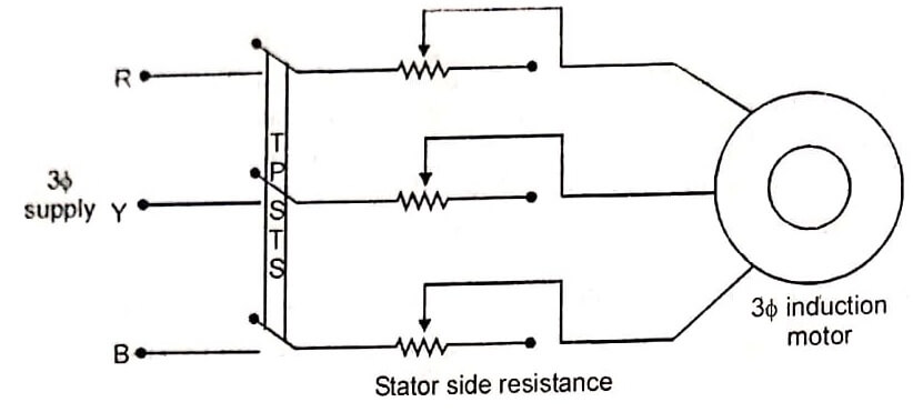
The reduced voltage limits the starting current. If the voltage across the terminal is reduced by 50%, then the starting current is reduced by 50%, but torque is reduced to 25% of the full voltage value.
Autotransformer starter
Figure shows an autotransformer starter. This starter is used to give a reduced voltage to the 3 -phase induction motor to limit the starting current. The reduced voltage is obtained by an auto transformer. The supply is given to terminals 1,3 and 5 of the movable handle and the motor is connected to 2,4 and 6 of handle through an OLRC (Over Load Release Coil). Low voltage protection is given to the motor by UVRC.
Operation
When the handle is at start position, the motor is connected through the auto transformer. Therefore a reduced voltage is applied and hence starting current is reduced. When the motor gets 80% of the normal speed, the handle is moved to RUN position. At this position, the motor receives full line voltage.
Over Load Protection
When motor current exceeds the preset value, the over load relay coil (OLRC) is energized high enough to operate the contactor S1. Hence supply. is switched off.
Low voltage protection
The Under Voltage Relay Coil (UVRC) is connected across two lines. When supply voltage goes low or fails, UVRC de-energises and releases the handle to OFF position.
Star-delta starter
Figure shows a star-delta starter. This method is used in motors which are built in, run normally with a delta connected stator winding. ‘it consists of a two way switch which connects the motor in star for starting and then in delta for normal running.
When the two way switch is at START position, the stator windings are connected in star. Therefore the applied voltage is reduced by a factor of 1/√3. For star connection Vph = VL/√3. Hence the starting current is reduced.
When the motor speed reaches 70 to 80% of normal speed, the switch is changed to RUN position where the motor is connected in delta. Therefore full voltage is applied to the motor in the running condition.
Rotor resistance starter
Figure shows a rotor resistance starter. This starter can be used only for slip ring induction motor. As shown in figure external or starting resistance is connected in the rotor terminals.
In this method, the motor is always started with full line voltage, applied across the stator terminals. The value of starting current is adjusted by introducing a variable resistance in the rotor circuit.

At starting, the full resistance is included and hence the starting current is reduced. The resistance is gradually cut out of the rotor circuit as the motor gathers speed.
- See More : Methods of voltage control
- See More : Alternator voltage regulator
- See More : Design of transformer
