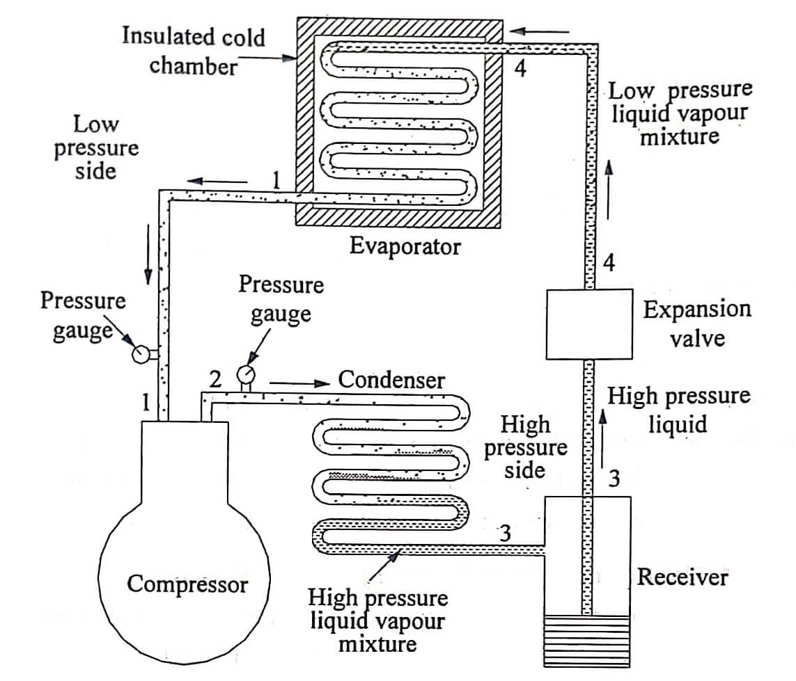
Vapour compression refrigeration system uses a liquefiable vapour as the refrigerant. In this system, the refrigerant used alternatively undergoes a change of phase from vapour to liquid and liquid to vapour during the cycle. In this, the isentropic expansion of Carnot cycle is replaced by a throttling process, expansion in a valve or capillary tube. A simple vapour compression refrigeration system is shown in fig.
The latent heat of vapourisation is utilized for absorbing the heat from low temperature space and transfers it to surrounding so that the Space is maintained at a temperature lower than that of surrounding.
Compressor
The main function of compressor is to increase the pressure and temperature of the refrigerant above atmospheric. The compressor used here is of reciprocating type.
Condenser
The condenser is used to cool the vapour and the vapour will be converted into liquid.
Receiver
The receiver is a storage tank, which stores the liquid.
Expansion valve or Throttle valve
The valve is used to reduce the temperature and pressure of the liquid refrigerant.
Evaporator
Evaporator causes the cooling effect in the refrigeration space by absorbing the heat from the space. It is made up of copper coils.
Working:
The high pressure vapor refrigerant from the condenser enters the expansion or throttle valve where it expands to the required pressure. During expansion pressure is reduced and the vapour becomes partially converted to liquid and produces cooling effect. This process is represented in p-h diagram as 3-4.
A mixture of low temperature vapor and liquid from expansion valve is then enters the evaporator and absorbs heat from the space to be refrigerated. Thus the “Refrigerating effect” is obtained. This process is represented in p-h diagram as 4-1.
Because of this, liquid becomes vapour (state 1) and this vapour enters the compressor. There it is compressed, thus the pressure goes up. This process is represented in p-h diagram as 1-2. This high pressure vapour enters the condenser. There, it looses its latent heat and becomes liquid. (Process 2-3) The liquid refrigerant is stored in a receiver and supplied to the expansion valve, and the cycle continues.
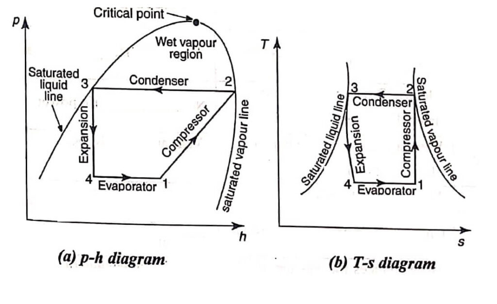
The above processes are represented on a p – h and T-s chart as shown in fig. (a) and (b) respectively.
Vapor Absorption Refrigeration System
In recent years, vapour absorption system becomes more interest due to its potential use as part of power saving plant. Also, it uses more environment friendly refrigerants than current vapor compression system. This used heat energy instead of mechanical energy as in vapour compression system. This system differs from vapor compression system in such a way that the compressor is replaced by an absorber and generator. The absorber absorbs the refrigerant and mixes it with the weak solution to produce strong solution. The function of generator is to heat the strong solution to form vapour of the refrigerant.
There are two types of vapor absorption refrigeration systems depending on the refrigerant and absorbent.
- Ammonia-Water system
- Lithium bromide-Water system
Vapour Compression Refrigeration System Vs Vapor Absorption System
| Sl.No | Vapour compression system | Vapour absorption system |
| 1. | Electric Power is needed to drive the system. | No need of electric power. |
| 2. | Wear and tear is more because of moving components. | Wear and Tear is less |
| 3. | Tonne capacity is low. | Tonne capacity is high. |
| 4. | Charging of refrigerant is simple | Charging of refrigerant is difficult. |
| 5. | More chances for leakage of refrigerant. | There is no leakage of refrigerant. |
| 6. | Mechanical energy is supplied. | Heat energy is supplied |
| 7. | Performance at part load is poor. | At part loads, the performance is not affected. |
| 8. | Space requirement is more. | Space requirement is less. |
| 9. | Energy requirement is low. | Energy requirement is high. |
| Read More Topics |
| Boiling water reactor |
| Ocean Thermal Energy Conversion |
| Overfeed stokers classification |
| High pressure boilers |
