Need for Voltage and Frequency Regulation in Power System
A power system is said to be well designed if it gives a good quality of reliable supply, which means that the voltage levels must be within reasonable limits. Practically, all the equipment on the power system are designed to operate satisfactorily within voltage regulation variations of around 5%. If the voltage variations is more than a pre-specified value, the performance of the equipment is also sacrificed.
The voltage at the generating stations and the frequency decides the kilowatt loading of the generating stations and the loading through the interconnectors (a number of power stations are interconnected through interconnectors.
Need for Voltage Regulation in Power System
Knowledge of voltage regulation helps in maintaining the voltage at the load terminals within prescribed limits under fluctuating load conditions, by employing suitable voltage control equipment. The following points are to be considered.
- The transmission lines and the distribution lines need voltage control at various stages to maintain the voltage at the last consumers premises within permissible limits.
- Variations in supply voltage are detrimental in various aspects.
- Below normal voltage substantially reduces the light output from incandescent lamps. Above normal voltage reduces the life of the lamps.
- Motors operated at below normal voltage draw abnormally high currents and may overheat, even when carrying no more than the rated horse power load.
- If the voltage of the system deviates from the nominal value, the performance of the device suffers and its life expectancy drops.
- The real line losses depend as much upon the reactive line as upon the real line power flow. The reactive line flow depends upon line end voltages.
- By adjusting the excitation of the generator at the sending end below a certain limit may result in instability of the system and excitation above certain level will result in overheating of the rotor.
- Service voltages are usually specified by a nominal value and the voltage maintained is ±5% of the nominal value.
Need for Frequency Regulation in Power System
Knowledge of frequency regulation helps in maintain the system frequency i.e., speed of the alternator within prescribed limits fluctuating load conditions, by using speed governor and integral controller. In a network, considerable drop in frequency occurs due to high magnetizing currents in Induction motors and transformers. The following points to be considered.
- In any power system, if the frequency changes there won’t be required receiving and voltage. If we connected two systems in parallel, it will spoil the system.
- The generator turbines, particularly steam driven ones are designed to operate at a verprecise speed.
- Most of AC motors run at a speed that are directly related to the frequency.
- The overall operation of a power system can be much better controlled if the frequency error is kept within strict limits.
- A large number of electrically operated clocks is a function not only of a frequency error, but actually of the integral of this error.
- Constant turbine speed is an important requirement. The velocity of the expanding steam is beyond our control and the turbine efficiency requires perfect speed match.
- Unusual deviations in the frequency can be detected earlier.
- When two system working at different frequencies are to be tied together to make same frequency, frequency converting stations or links are required.
BASIC P-F AND Q-V CONTROL LOOPS
- Static changes in ΔP, in the real bus power affect the bus phase angle, and not the bus voltage magnitudes. This change affects the real line flows, and not the reactive line flows.
- Static changes ΔQ, in the reactive power affect the bus voltage magnitude and the phase angle. This change affects the reactive line flows, and not the real line flows.
- Static changes in the reactive bus power affects the bus voltage at the particular bus and little effect on the magnitude of voltage.
Q-v Control Loop
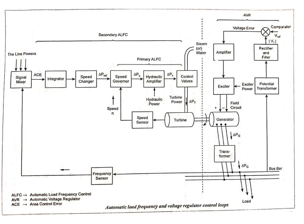
The automatic voltage regulator circuit or Q-v control loop as shown.
This loop is used for voltage control. This bus-bar voltage (say, 11kV) is stepped down using a potential transformer to a small value of voltage. This is sent to the rectifier circuit which converts the A.C voltage into D.C. voltage and a filter circuit used in this removes the harmonics. The voltage V1, thus rectified is compared with a reference voltage Vref in the comparator and a voltage error signal is generated. The amplified form of this voltage gives a condition for the exciter to increase or decrease the field current based on its polarity. The output of the generator is stepped up using a transformer and fed to the bus bar. Thus the voltage is regulated and controlled in this control loop circuit.
P-f Control Loop
This control loop circuit is divided into primary and secondary Automatic Load Frequency Control (ALFC) loop structures as shown.
Primary ALFC
The circuit primarily controls the steam value leading to the turbine. A speed sensor senses the speed of the turbine. This is compared with a reference speed, governor whose main activity is to control the speed of the steam by closing and opening of the control value i.e., if the differential speed is low, then the control valve is opened to let out the stem at high speed, thereby increasing turbine’s speed and vice versa. The control of speed in turn controls the frequency.
Secondary ALFC
This circuit involves a frequency sensor that senses the frequency of the bus bar and compares it with Tie line power frequencies in the signal mixer. The output of this is an Area Control Error (ACE) which is sent to the speed changer through integrator. The speed changer gives the reference speed to the governor. Integral controller is used to reduce the steady state frequency change to zero. After this part of the circuit, is the introduction of the Primary ALFC loop whose function has already been described.
Thus, the two loops together help in controlling the speed which in turn controls the frequency, since N α f.
| Read More Topics |
| Types of Deaerator |
| Design of Transformer |
| Power System Security |
| Point to point links |
| Reactive Power and Voltage control |