WELDED JOINTS
Welded joints are classified according to the relative positions of two components to be joined. There are five basic welded joints types.
- Butt joints:
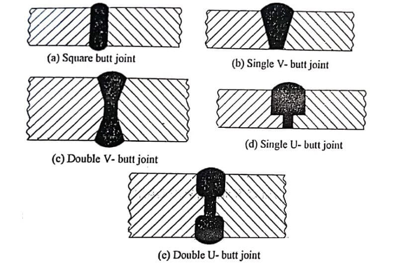
It is used to join the ends or edges of two plates. The surfaces of plates are located in the same plane. The edges of the plates are beveled depending on their thickness. Table indicates the thickness of plates for which different welded joints types of butt joints are used.
- Lap joints:
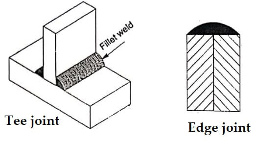
In a lap joints, the two plates are overlapped each other for a certain distance. Then the edge of each [late is welded to the surface of the other surface as shown in image. Such a weld is also called fillet weld. A fillet weld consists of approximately triangular cross section joining two surfaces at right angle to each other, sometimes, it may also be reinforced to increase the load capacity of the weld per unit length as shown image.
| Types of joints | Thickness of plate (mm) |
| Square butt joint | 1-6 |
| Single V butt joint | 6-20 |
| Double V butt joint | 12-60 |
| Single U butt joint | 20-60 |
| Double U butt joint | 30-60 |
DESIGN CONSIDERATIONS IN WELDING
- Design for welding:
It refers that the product should be designed from the start as a welded assembly, but not as a casting or forging or other formed shape.
- Design for minimum parts:
Welded assemblies should consist of fewest numbers of parts possible. Example: It us usually more cost efficient to perform simple bending operations on a part than to weld an assembly from flat plates and sheets.
Arc welding design guidelines:
- Good fit-up of parts is to maintain dimensional control and minimize distortion. Sometimes, machining is required to achieve satisfactory fit-up.
- Assembly must allow access for welding gun to reach welding area.
- Design of assembly should allow flat welding to be performed as much as possible since it is the fastest and most convenient welding position.
Resistance welding design guidelines:
- Low-carbon steel sheet up to 0.125 (3.2 mm) is ideal metal for resistance spot welding.
- Additional strength and stiffness can be obtained in large flat sheet metal components by the following methods.
- Spot welding reinforcing parts into them
- Forming flanges and embossments.
- Spot welded assembly must provide access for electrodes to reach welding area.
- Sufficient overlap of sheet metal parts is required for electrode tip to make proper contact.
DESIGN OF BUTT WELD JOINTS
Butt-welded joints are designed for tensile or compressive forces. The types of butt joint formed between two plates and the minimum weld size depends on the thickness of plate. Table gives the guidelines for selection of minimum weld size of butt joints.
WELDABILITY
Weldability is also known as joinability of a material. It refers the ability to weld. It is defined as the capacity of a metal or combination of metals to be welded into a suitable structure, and for the resulting weld joint(s) to possess the required metallurgical properties to perform satisfactorily in intended service.
Many metals and thermoplastics can be welded but some are easier to weld. A material’s weldability is used to determine the welding process and to compare the final weld quality to other materials. The three most common weldable metals are mild steel, stainless steel and aluminium.
Good weldability is characterized by the following characteristics:
- Ease with which welding is accomplished.
- Absence of weld defects, and
- Strength, ductility and toughness in welded joint.
Weldability Factors – Welded Joints types
Some metals or metal combinations can be readily welded by one process but they are difficult to weld by other processes. The weldabilty of material depends on the following factors:
- Carbon Equivalent Value (CEV):
Carbon Equivalent Value (CEV) is used for rating of weldability of ferritic flow alloy steels. It takes into account the equivalent additive effects of carbon and other alloying elements on a particular characteristic of steel. Steel with a low carbon equivalent has a better weldability than steel with a high value.
A commonly used formula to calculate CEV based on a publication of the International Institute of Welding (IIW) is as follows.
CEV = C+Mn/6 + (Cr + Mo +V)/5 + (Cu + Ni)/15
From this equation the weldabilty based on a range of CE values can be defined as follows;
Carbon equivalent value (CEV) Weldability
Up to 0.35 Excellent
0.36-0.40 Very good
0.41-0.45 Good
0.46-0.50 Fair
Over 0.50 Poor
In wedding, equivalent carbon content (CE) is used to understand how the different alloying elements affect the hardness of steel being welded.
WELDABILITY OF ALUMINIUM
Aluminium and its alloys are routinelt welded and brazed in industry by a variety of methods. Welding aluminium alloys is not more difficult or complicated than welding steel. It is different and requires specific training. Aluminium and its alloys are easy to weld.
The most common commercial aluminium and aluminium alloy welding methods use an electric arc with either a continuously fed wire electrode or a permanent tungsten electrode plus filler wire. The arc is protected by argon gas to shield the weld pool and electrode from surrounding atmosphere. Arc welding is easy to use, attains a high temperature, provides high heat input and easy to regulate.
The weldability of aluminium alloys varies significantly dependisng on the chemical composition of the alloy used because aluminium alloys are prone to hot cracking and to combat. So, welders increase the welding speed to lower the heat input. Preheating reduces the temperature gradient across the weld zone and thus, it helps reduce hot cracking but it can reduce the mechanical properties of the base.
So, the proper selection of filler allot is required. Also, aluminium alloys should also be cleaned before welding to remove all oxides, oils and loose particles from the surface to be welded.
The different wrought aluminium alloy families are split into two groups such as non-heat treatable and heat treatable. Unless the base metal is in the annealed or cast condition, fusion welding will decrease the strength of both heat and non-heat treatable alloys.
Various welding processes are used to join aluminium including the fusion methods GMAW (standard MIG, plasma and pulse) and GTAW (standard TIG and plasma). All methods are producing high quality, all-position welding, manual, mechanized or fully automatic. Also, resistance and advanced processes such as solid state and friction stir welding are used. A choice of process is based on technical and economic reasons.
For most structural economical and quality welds, TIG and MIG are recommended for aluminium. TIG welding is generally preferred for light gauge work up to 6mm and for pipe work and intricate assemblies where excellent control over weld appearance and penetration is possible.
Thicker material can be welded using TIG but very high current is needed and very slow weldisng speed is required. Butt, filled, lap and edge welds are carried out using TIG welding. For welding two dissimilar thicknesses materials, TIG welding is preferred.
MIG welding is preferred for thicker sections having 75 mm where high productivity is needed for economic reasons. Limitations of MIG welding process are the controlling of penetration being difficult and edge welds are not possible. TIG welding is preferred for repair welding of aluminium castings but MIG is preferred when welding castings to sheet and plate and extrusions.
Good seam welds can also be used to weld aluminium and its alloys. Good TIG seams have a regular ripple finish. Also, there is a narrow and white de-oxidised zone on both sides of the seam. Good MIG seams have a uniform fine ripple finish on the seam with an excellent transition to the basic material.
Before welding aluminium, exposing the workpiece to preheat is good for better weldability. At the same time, too much preheat can degrade the mechanical properties of the aluminium.
When welding, the operator sets up residual stresses around the vicinity of the weld because the molten material shrinks as it solidifies. It distorts and creates dimensional instability. To avoid it in aluminium, operators perform stress relieving by heating the material hot enough to allow the aluminium atoms to move around.
WELDABILITY OF COPPER – Welded Joints types
Copper alloys can be welded joints types with most of the conventional welding processes. Mainly, are welding processes and gas shielded are methods are the most common.
Copper alloys:
There are three separate grades of pure copper:
- Oxygen-free copper:
It has less than 0.02% oxygen which is mostly used for pressure vessel and heat exchangers. Oxygen-free copper is the most readily weldable.
- Copper oxides:
The use of tough pitch copper can result the embrittlement of the heat affected zones due to oxides films forming on the grain boundaries.
- Phosphorus deoxidized copper:
It produces less porosity problem during autogenous welded joints types.
Welding Processes for Copper and its Alloys
In manufacturing, copper is joined by are welding. Arc welding can be performed using shielded metal arc welding (SMAW), gas-tungsten arc welding (GTAW), gas-metal arc welding (GMAW), plasma arc welding (PAW) and submerged arc welding (SAW).
Clean, grease-free wires and rods and high purity shield gases are required when TIG or MIG welding. Shielding gases for welding are argon, helium and nitrogen or mixes of two or more of these gases. Pure argon may be used for TIG welding up to a thickness of some 2 mm and for MIUG welding, it is up to approximately mm.
Shielded metal arc welding is used to weld a wide range of thickness of copper alloys. Covered electrodes for shielded metal arc welding of copper alloys are available.
TIG welding is the best suited for copper and copper alloys because of its intense arc which produces an extremely high temperature at the joint and a narrow heat-affected zone (HAZ). TIG is used to join coppers and copper alloys for thickness less than 3mm while MIG is selected for section thickness above 3 mm and for joining of aluminium bronzes, silicon bronzes and copper-nickel alloys.
Plasma arc welding is more suitable for coppers and copper alloys. Argon, helium or mixtures of the two are used for welding of all alloys. Hydrogen gas should never be used when welding coppers.
Submerged arc welding is used for welding of thick gage material such as pipe formed from heavy plate can be achieved by continuous metal-arc operation under a granular flux. Commercially available fluxes should be used for copper-nickel alloys.
| Read More Topics |
| Electroslag welding pros and cons |
| Laser beam welding process |
| Magnetic particle inspection in welding |
| Welding process gas and arc |
