The method known as SCADA has long been used to control transmission systems, providing the operational flexibility and speed required for efficient and reliable performance. The use of SCADA in the distribution system is becoming increasingly important as utilities move into a deregulated, competitive environment. The acronym SCADA is being replaced by the generic term distribution automation (DA), which incorporates the principle of computers operating switching and other control devices automatically in response to preprogrammed events in the system.
Automated switching of distribution feeder circuits provides significant improvements in reliability, enhances operational flexibility, and increases productivity of both utility personnel and distribution lines.
Automated feeder switching systems utilize controls, sophisticated algorithms, and data communications to go beyond the reliability benefits of more traditional reclosers and automatic sectionalizers. An automated switching system can be programmed to not only reduce outage times, but do so without subjecting unfaulted circuits to “bumps” caused by intentional closing into faults required by fault-detection or troubleshooting schemes.
Further, an integrated fault isolation and restoration system can incorporate real time evaluation of prefault loads into the algorithm to prevent overloading of a backup circuit when transferring load from a faulted circuit. This allows the utility planner more flexibility in circuit design by increasing the amount of load that can normally be carried by a given circuit.
Such systems, with current and voltage monitoring, also provide the utility with a convenient way to monitor distribution feeder circuits, thus enabling the utility to take immediate action in the event of current or voltage excursions exceeding normal operating limits. This, in turn, results in improved power quality and service for the customer.
Automated feeder switching systems can also provide the means to optimize feeder and substation loading by enabling the shifting of load from one feeder to another in a very short time frame. This same capability can yield hard-dollar cost savings associated with deferment of capital projects when coupled with planning practices that take advantage of the new technologies.
With the increasing power of computers and improving communications, it is certain that auto mated feeder switching systems will provide benefits that have yet to be considered in the electric utility industry.
Examples of Automated Feeder Switching Systems
A large investor-owned electric utility in New York needed to dramatically improve reliability in response to a challenge from the New York public utility commission. After analyzing its system as well as the nature and locations of faults, it was decided that an automated feeder switching system would provide the quickest route to needed improvements in electric service reliability.
A typical MES feeder “loop” is shown in Fig. It consists of two circuits joined by a normally open tie switch. In turn, each feeder circuit will have a normally closed automated switch installed at the electrical half-way point on the circuit. All switches are equipped with voltage and current monitoring as well as communication and control units (CCUs) housing the switch controls, power supplies, remote-terminal units (RTUs) and radios for establishing communication with the master station.
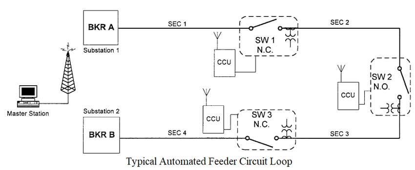
Faults occurring in Sec. 2 will result in a trip of substation breaker BKR A. The control at switch SW1 will sense the passage of fault current and the subsequent loss of voltage precipitated by the opening of BKR A. A sectionalizing algorithm will initiate and open the switch after a predetermined time delay set to coordinate with the recloser interval of BKR A. The station breaker is reclosed to determine if the fault condition is temporary or permanent.
A typical reclosing breaker may reclose up to 3 times on some systems. Once SW1 is open and the fault is isolated, BKR A will reclose, restoring service to the customers in Sec. 1. At this point, the crew can proceed directly to SW1 and commence the search for the fault from there, further reducing the amount of time for fault location.
Faults occurring in Section 1 will result in a lockout of substation BKR A. At this point, SW1 will see a loss of voltage and transmit an alarm to the master station. The master will then interrogate SW1 and find that it saw loss of voltage, but no overcurrent. This condition indicates a section 1 fault.
The master station will then initiate the section 1 fault algorithm and interrogate SW1 to determine the load in section 2 just prior to the fault. The master then interrogates SW3 for load information. If the addition of section 2 load to the current load on section 3 will not result in an overload condition, then the master station will instruct SW2 to close, restoring service to section 2.
The MES system can be operated in three modes. The first is traditional SCADA, where the dispatcher must identify and analyze circuit conditions before deciding on restoration procedures, which must then be sent to the field devices individually.
In the second mode, the master station computer will identify and analyze the circuit condition and make an operational recommendation to the dispatcher, who can then choose to accept the recommendation and execute a simple acknowledge command which will automatically issue appropriate commands to field devices.
The third mode identifies and analyzes circuit conditions and automatically issues commands to field devices to isolate faulted sections and restore service to unfaulted sections. It should be noted that the system can utilize up to seven switching devices on a given circuit loop similar to that shown in Fig. The figure was simplified for clarity in this example.
A large metropolitan utility serving customers in and around Chicago wanted to improve electric service. However, they did not have a SCADA master station at the beginning of the project and needed a way to improve service without installing one. In this case, the utility installed a system which utilizes distributed intelligence in the switch controllers to do all analysis as well as fault isolation and circuit restoration.
Such a system operates in much the same way as described in the example above. The key difference is that this system does not utilize the first two modes of operation: traditional SCADA and suggesting operational recommendations. The advantage is the ability to install the system without the need for a communications network or SCADA master station.
This system does its work automatically without human intervention or the need for a communication system. It should be noted that the system can be easily disabled in the field for line work if desired and can be upgraded to work with a master control station.
Automated Switches
A key part of an automated feeder switching system is the automated switch. The term “automated” in this context means the switch is designed for use on an automated or SCADA system. In order to be automated, existing switches may be retrofitted with motor operators, current and voltage sensors, RTUs and communication devices to allow the remote operation necessary to realize the benefits available with automated feeder switching systems.
However, switches designed for occasional, manual operation may not be entirely suitable for operation on an automated distribution circuit feeder. Manual switches are typically not designed to be operated the hundreds of times required by a fully automated system over the life of a typical switch. Nor are they ordinarily designed for duty cycle fault-closing to allow the system operator to inadvertently close into a fault from the SCADA master station and still leave the switch in an operable condition.
More recently, switches designed specifically for automation have appeared in the market. Such switches incorporate design features that make them particularly applicable for use in an automated feeder switching system:
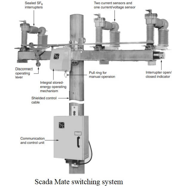
- Duty-cycle fault-closing allows the switch to be closed into a typical fault several times before experiencing damage severe enough to render the switch inoperable.
- Integrated voltage and current sensors provide the ability to monitor voltages, currents, and loads that are in turn used as inputs to algorithms to effect automated switching for fault isolation and restoration and for shifting loads for circuit optimization.
- Integrated operating mechanisms enable the switches to be operated remotely via computer commands. Integration with the switch ensures optimum operation without the need for cumbersome ground to switch linkages.
- Integrated load interrupters should be designed to allow operation under any weather conditions since it will not be possible to visibly inspect the switch for ice or other problems prior to operation.
- Integrated control power sources eliminate the need to rely on locally available control power sources or to install such power sources.
- Integrated visible air gap isolation provides the visible air gap when needed for certain types of line work.
In addition, an associated control package should include switch operating controls, a local/remote switch, backup power for dead line SCADA operation, a remote-terminal unit, and data-communication devices. The entire package should be assembled and tested for proper operation by a single supplier to eliminate the need for the utility to perform the integration.
The control box should be separately located from the switch to allow access by technicians who are not qualified in high-voltage operations. In underground switchgear applications, the control should be isolated from the high voltage compartments of the switchgear.
| Read More Topics |
| Series capacitor voltage |
| High energy rate forming process |
| Electrical machine design |
