A control system in mechatronics refers to a group of physical component connected or related in such a manner as to command direct or regulate it selfe or another system. The physical components may be of electrical, mechanical, hydraulic, pneumatic, thermal or chemical in nature.
Several key terms & elements of the control system are :
- Reference variable or input : Stimulus or excitation applied to a control system from an external source, usually in order to produce a specified response from the system.
- Output: The actual response obtained from the system.
- Feedback: That portion of the output of a system that is returned is modify the input and thus serve as a performance monitor for the system.
- Error: The difference between the input stimulus and the output response. Specifically, it is the difference between the input and the feedback.
- Disturbance: Any signal other than the reference which affects the system performance.
- Actuating signal: The difference between the feedback signal and reference signal.
- Control or Feed Forward Elements: Those components directly connected between the controlled output and the referenced input.
- Controlled Output: The variable (temperature, position, velocity, shaft angle, etc.) that the system seeks to guide or regulate.
- Feedback Elements: Those components required to establish the desired feedback signal by sensing the controlled output.
Example of control system
Consider an industrial cooler in a food processing unit which is required to maintain the temperature of unit at particular predefined level. In this control system, the input is the temperature of the unit at present which is received from temperature sensor and the output is the particular predefined temperature of the unit, i.e., the required temperature is set in the thermostat or controller and the compressor of the cooler unit adjusts itself by comparison of input data and output data to pump refrigerant through evaporator and so produce the required temperature in the unit.
This is an example of feedback control in which the sensor signals are feedback from the output in order to modify the reaction of the pump to switch on or off.
Consider another example of steering control in automobiles. The vehicle direction is controlled by wheel orientation which is achieved by controlling steering wheel manually.
This automobile steering system consisting of steering wheel, steering gear, linkages, and wheel, constitutes a control system. In this system, the input is the steering wheel position/rotation and the wheel orientation is the controlled variable or output.
The route of the vehicle is determined by the driver and by properly adjusting/controlling the steering wheel the vehicle is maintained to run on the road in the desire direction.
The driver monitors and compares the road condition and accordingly takes the decision to control the vehicle direction through steering wheel.
This is also an example of feedback control system. The input (steering wheel position/rotation) is modified according to the output (wheel orientation) by visually monitoring (feedback data) the road condition.
Non-engineering systems such as human body can also be considered as a control system. Normal functioning of human body is controlled by blood pressure and temperature of the body. Both are kept at constant value by means of physiological feedback provided by many other sub-systems.
The illustration of feedback principle of human body blood pressure and temperature control. Therefore, the human body is a highly advanced feedback control system. This feedback system makes the human body relatively insensitive to external disturbances, the enabling it to function properly in a changing environment.
Other examples of applications of control systems include, but not limited to:
- Idle speed control system of an automobile.
- Print wheel control system of a printer
- Temperature control of an electric furnace or oven.
- Sun tracking control of solar collector
- Aircraft rudder control system
- Gun or missile director
- Missile guidance system
- Laser-guided projectiles
- Automatic pilot
Open-loop Control Systems
Control systems are classified into two groups:
- Open loop control systems
- Closed loop or feedback control systems
Open loop systems are systems in which the output of a system is not used as a variable to control the system. In other words, open systems are systems in which input to the system is not controlled by the present output.
In an open-loop system, the output of this system is not fed back into the input to the system for control or operation. An open system is essentially a feedforward system. The system is an “open” system because it does not have a feedback loop in its control.
There are many reasons to use open loop control such as simplifying the control system, quicker response of the system, to reduce the possibility of oscillation and sometimes to lower cost.
Examples of open-loop control system
The basic elements of this system are an amplifier and a controller as shown in figure. The amplifier receives a low-level input signal and amplifies it enough to drive the controller to perform the desired job.
As an example consider automatic bread toaster. In this system, when the system is switched ON, the heating element in the toaster heat the bread for particular present time and then automatically it get switched OFF and ejects the bread. Here there is no feedback of data of whether the bread is toasted properly or not.
Another example of an open-loop control system is a chemical addition pump with a variable speed control. The feed rate of chemicals that maintain proper chemistry of a system is determined by an operator, who is not part of the control system.
If the chemistry of the system changes, the pump cannot respond by adjusting its feed rate (speed) without operator action.
Consider an example of the use of open-loop control system is in the control of the wing surfaces on a modern fighter plane. The closed loop implementation would make the control much slower.
However, if there is a disturbance on the output side of the process, control action does not take it into consideration. In order to remove this limitation, feedback has to be provided.
Open loop control systems are not as commonly used as closed-loop control systems because they are less accurate. All control systems operated by preset timing mechanisms are open loop.
Advantages and disadvantages of open-loop control system
Advantages
- Simple and cost effective construction
- Easy maintenance because of no complex electronic circuits
- Good stability.
- Good reliability.
- Quicker response.
- No calibration problem.
- Convenient when output is difficult to measure or economically not feasible.
Disadvantages
- Less accurate.
- Presence of non-linearities causes malfunctioning.
- Slow because of manual control.
- Optimisation in control not possible.
- System is affected by internal and external disturbances.
Closed-loop Control Systems
Closed-loop system uses on a feedback loop to control the operation of the system. In closed loop or feedback control the controller notices what actually takes place at the output end and drives the plant in such a way as to obtain the desired output.
Closed loop control systems are the type most commonly used because they respond and move the loads they are controlling quicker and with greater accuracy than open-loop systems. The reason for quicker response and greater accuracy is that an automatic feedback system informs the input that the desired movement has taken place.
The basic layout of a feedback or closed-loop control system. The essential elements of this system are:
- The plant is the system or process through which a particular quantity or condition is controlled. This is also called the controlled system.
- Measuring unit: sensors, estimators and signal conditioners are the part of measuring unit.
- The control elements are components needed to generate the appropriate control signal applied to the plant. These elements are also called the “controller”
- Comparison element or Error junction: where the desired system outputs and the measured or estimated outputs are compared to generate the error signal. Error signal is the difference between the reference value and the measured value.
- Correction element or actuator: produces a change in the plant or process to correct the controlled plant.
- The feedback elements are components needed to identify the functional relationship between the feedback signal and the controlled output.
Below are several terms associated with the closed-loop control systems.
- The reference point is an external signal applied to the summing point of the control system to cause the plant to produce a specified action. This signal represents the desired value of a controlled variable and is also called the “setpoint.”
- A controlled variable is the process variable that is maintained at a specified value or within a specified range. The controlled output is the quantity or condition of the plant which is controlled.
- The feedback signal is a function of the output signal. It is sent to the summing point and algebraically added to the reference input signal to obtain the actuating signal.
- The actuating signal represents the control action of the control loop and is equal to the algebraic sum of the reference input signal and feedback signal. This is also called the “error signal.”
- The manipulated variable is the variable of the process acted upon to maintain the plant output (controlled variable) at the desired value.
- The disturbance is an undesirable input signal that upsets the value of the controlled output of the plant.
In the system, the actual output is fed back and compared with the desired response. The resulting error is the basis for the application of a control signal to the plant.
The controller generates the control signal on the basis of the error. If a mechanical signal has to be applied to the plant, it is generated by an actuator from the output of the controller.
In this arrangement, the control signal takes the actual controlled variable into account including disturbances if any. The plant is driven (by the control signal) until the error is reduced. This is the principle of feedback control in which feedback is negative.
From the above description it is clear that a closed loop control system must be capable of the following:
- Accepting an order that defines the desired result.
- Determining the present conditions by some method of feedback.
- Comparing the desired result with the present conditions and obtaining a difference or an error signal.
- Issuing a correcting order (the error signal) that will properly changes the existing conditions to the desired result
- Obeying the correcting order.
Examples of closed-loop control system
Few examples are already discussed in the previous topics such as industrial cooling control system and automobile steering control system. Yet, another example for closed loop control system is room heating system in western countries. The thermostat (input) calls for heat.
The heating coil (output produces heat and distributes it. Some of the heat is “fed back” to the thermostat. When this “feedback” raises the temperature of the room to that of the thermostat setting, the thermostat responds by shutting the system down until heat is again required.
In such a system, the feedback path, input to output and back to input, forms what is called a “closed loop.”
In this system, the various elements are:
Plant or process – the heating of room by electrical coil
Controlled variable – the room temperature
Reference input – the desired room temperature
Comparison element – the electronic logic-circuit
Error signal – the difference between the current and required temperatures
Controller – the switch
Correction element – the thermostat
Measuring element – the temperature sensor attached with thermostat
Advantages and disadvantages of closed-loop control system
Advantages
- Closed loop control, with the appropriate sensor, provides much greater stability.
- Closed loop control will also give much better repeatability.
- Closed loop control overcomes temperature and hysteresis effects.
- Closed loop control can perform a task faster than open-loop.
- Good reliability.
- Optimisation in control is possible.
Disadvantages
- Generally closed-loop control systems are complicated in construction.
- Cost of the system is higher.
- Sometimes closed loop control systems may become unstable.
Comparison between Open-loop Closed-loop Systems
A comparison would show the following differences between open loop and closed loop control systems.
| SI. NO |
Open-loop |
Closed-loop |
| 1.
2. 3. 4. 5. 6. 7. 8. 9. 10. |
Open loop operation and dose not uses on a feedback to control the operation of the system.
The effects of known disturbances alone can be countered. Other disturbances cannot be taken into account. As long as the controlled plant is itself stable, the control system cannot system cannot become unstable. Less accurate Simple in construction. Presence of non-linearities causes malfunctioning. Slow response because of manual control. Optimisation in control not possible. Easy maintenance because of no complex electronic circuits. Cost of the system is less. |
Closed loop operation using negative feedback.
The effects of disturbances are countered by virtue of negative feedback. Closed loop operation can be unstable even if the plant is stable. More accurate. Complicated in construction. Usually performs accurately even in the presence of non-linearities. Closed loop control can perform a task faster than open-loop. Optimisation in control is possible. Difficult to maintain and repair. Cost of the system is higher. |
Automatic Control Systems
An automatic control system is a preset closed-loop control system the require no operator action. Most of the closed loop control systems are automatic in nature. This assumes the process remains in the normal range for the control system. Various applications of automatic control systems are explained under.
Examples of automatic control system
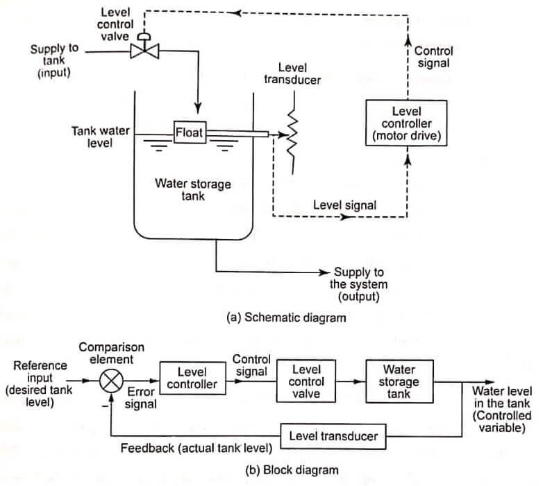
Example 1: Automatic tank-level control system
An example of automatic tank-level control system. The control system maintains water level in a storage tank. The system performs this task by continuously sensing the level in the tank and adjusting a supply valve to add more or less water to the tank. The desired level is preset by an operator, who is not part of the system.
The level transducer measures the level within the tank by using float and potentiometer arrangement. The level transducer sends a signal representing the tank level feedback to the level control device (motor drive).
This feedback is compared with a desired level to produce the required control action that will position the level control as needed to maintain the desired level.
The level control device computes how far to open the supply valve to correct any difference between actual and desired tank levels. The block diagram of this system representing the signal flow to various elements including feedback.
In this system, the various elements are:
Plant or process – the water storage tank
Controlled variable – the storage tank level
Manipulated variable – the flow rate of the water supplied to the tank
Reference input – the desired tank level
Comparison element – the level controller
Error signal – the difference between the current and required water level
Controller – the level controller
Correction element – the level control valve
Measuring element – the level transducer
Example 2: Automatic temperature control system for lubricating oil
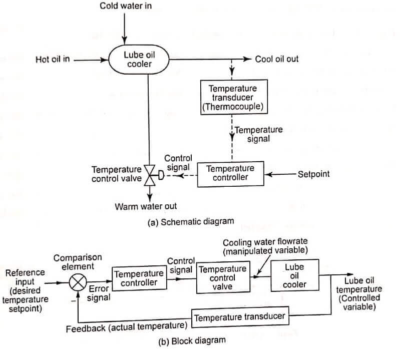
Another example of temperature control system for lubricating oil. Shows a schematic diagram of the lube oil cooler and its associated temperature control system. Lubricating oil reduces friction between moving mechanical parts and also removes heat from the components.
As a result, the oil becomes hot. This heat is removed from the lube oil by a cooler to prevent both breakdown of the oil and damage to the mechanical components it serves. The lube oil must be maintained within a specific operating band to ensure optimum equipment performance.
This is accomplished by controlling the flow rate of the cooling water with a temperature control loop. The temperature control valve.
The lube oil temperature is the controlled variable because it is maintained at a desired value (the setpoint). Cooling water flow rate is the manipulated variable because it is adjusted by the temperature senses the temperature of the lube oil as it leaves the cooler and sends an error signal that is proportional to the temperature controller.
Next, the temperature controller compares the actual temperature of the lube oil to the setpoint (the desired value). If a difference exists between the actual and desired temperature control valve, the controller will vary the control air signal to the temperature control valve.
This causes it to move in the direction and by the amount needed to correct the difference. For example, if the actual temperature is greater than the setpoint value, the controller will vary the controller will vary the control air signal and cause the valve to move in the open direction.
This results in more cooling water flowing through the cooler and lowers the temperature of the lube oil leaving the cooler.

Represents the block diagram of temperature control system for lubricating oil. The lube oil cooler is the plant in this example, and its controlled output is the lube oil temperature. The temperature transducer is the feedback element. It senses the controlled output and lube oil temperature and produces the feedback signal.
The feedback signal is sent to the summing point to be algebraically added to the reference input (the setpoint). The actuating signal passes through the two control elements: the temperature controller and the temperature control valve.
The temperature control valve responds by adjusting the manipulated variable (the cooling water flow rate). The lube oil temperature changes in response to the different water flow rate, and the control loop is complete.
Example 3: Automatic positioning system for a missile launcher
Another example of automatic control system is automatic positioning system for a missile launcher. Illustrates this system with block diagram. This is a feedback system designed to position the launcher quite accurately on commands from potentiometer.
Potentiometer sends a signal back to the amplifier which functions as an error detector. If there is error exist, it is amplified and applied to a motor drive which adjust the output shaft position until it agrees with the input shaft position and makes the error to zero value.
Here the input is the desired angular position, the output is the actual angular position, and the control system consists of the potentiometer power, amplifier, motor gearing between the motor and missile launcher, and the missile launcher.
Example 4: Automatic speed control system of a DC motor
An automatic speed control system of a DC motor is illustrated. The function of this system is to maintain the output speed of the motor relatively constant irrespective of the torque variation.
Here a tachometer is used as a transducer which transforms speed to voltage and is also used as a feedback element. When the output speed differs from the desired speed, the comparison element develops an error signal which adjusts the field current of the motor in order to restore the desired output speed.
| Read More Topics |
| Nuclear Power Plant |
| Hydro Electric Power Plant |
| Coal Cleaning Equipment |
| Steam Power Plant Layout and working |
| Vapour Compression |
