Pneumatic and Hydraulic Actuation Clamps
Generally, the above mentioned pneumatic and hydraulic clamps are actuated by mechanical means. Sometimes, these are actuated by hydraulic or pneumatic methods where large production quantities are required. It facilitates faster clamping, uniform and equalised clamping pressure and less operator fatigue. It also provides an accurate controlling over clamping pressure.
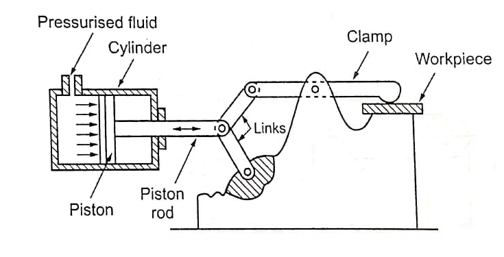
Hydraulic and pneumatic clamps are grouped under fluid power clamping since both use of fluids for generating clamping pressures. Fluid power clamps are generally actuated by cylinders. Image shows a clamping fixture with the clamping links attached to the cylinder piston and clamp.
During clamping of the workpiece the piston inside the cylinder is actuated by oil or air pressure, as shown in image. The piston rod connected to the levers of the clamp operates and exerts necessary pressure to the workpiece. For unclamping, the piston moves back thereby actuating the levers. The clamping pressure on the workpiece is released. Hence, the workpiece can be unloaded.
Fluid Power Clamp – Pneumatic and Hydraulic
Clamping pressure of all clamps will be equal when there are number of clamps actuated by a single control valve. The clamping pressure can be varied by regulating the pressure of the fluid. Higher pressure can be used for rough and heavy cuts. The pressure can be considerably reduced during light finishing cut.
There is a risk of sudden pressure drop when the failure of power will be. This problem can be eliminated by a providing a non-return valve in the pressure supply line. If the power fails, the non-return valve automatically is closed the passage between the pressure line and the cylinder.
Pneumatically operated clamps differ from hydraulically operated clamps in the size of the cylinder. Pneumatically operated clamps require larger cylinder than hydraulic one because of less pressure exerted by the air. A small hydraulic cylinder can exert higher pressure as the hydraulic fluid is incompressible.
Generally, pneumatically operated cylinders are not used where heavy clamping forces are required because extremely large cylinders would be required. But pneumatically operated clamps are convenient because most of the manufacturing Industries have a hi supply of compressed air. In a pneumatic clamping, compressed air is used as the fluid for actuating piston and links. The air is pressurised about 5 to 6 kg/cm². Generally, a large compressor is used to supply air to the entire machine shop. Pneumatic clamps used for light weight applications only and also where there are no load variations.
Air to Hydraulic Booster
In a hydraulic clamping, hydraulic oils are used as the fluid for actuating piston and links. Hydraulic oils are almost incompressible. Therefore, it will not cause much speed variations in hydraulic systems during the variation in load. The operating pressure of hydraulic system ranges from 0.7 to 25N/mm². Small compact cylinders are sufficient for developing nigh clamping force.
However, hydraulic cylinders are slow in operation in comparison with pneumatic actuators. Oil is recirculated in the system through a reservoir.
The hydraulic operation of a mechanism requires higher

Locating and Clamping Principles initial cost since each machine or fixture requires an individual cylinder and power unit.
In modern days, the system of both pneumatic and hydraulic operated clamps is used. For this purpose, air-to-hydraulic booster is used which converts low pressure air into high hydraulic pressure.
The principle of operation of air-to-hydraulic booster is shown in image. If the air cylinder piston is subjected to 5 N/mm² air pressure and the area of piston is 1000mm², a force of 5000N is placed upon the ram. If the ram diameter is 100mm-. the pressure upon the hydraulic oil must be 50N/mm. A hydraulic pressure of 50N/mm has been produced from 5N/mm² air pressure, i.e., has increased the pressure by a ratio of 10: 1. In general, the ratio of an air to hydraulic booster can be determined by dividing the area of air piston by the area of hydraulic ram. The high pressure output is calculated by multiplying the air pressure by the area ratio.
| Read More Topics |
| Fast breeder reactor |
| Boiling water reactor |
| Pressurised water reactor (PWR) |