There are three types of characteristics.
- Open circuit characteristics (OCC) or magnetisation characteristics (E2 versus If).
- Internal characteristics or total characteristics (E versus Ia).
- External characteristics or voltage regulated characteristics (V versus IL)
Separately excited DC generator characteristics
For a given dc generator it is clear that the induced emf is proportional to the flux and the speed. If speed is kept constant, and the flux is varied, the induced emf also varies
Since. 
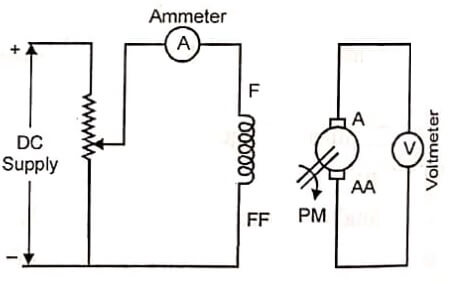
The variation of flux with the induced emf is called the no-load magnetisation curve or saturation curve or open circuit characteristics (OCC) of the generator. Since characteristics (OCC) of the generator. Since the measurement of flux is difficult, the curve is plotted between field current If and induced emf (Eg). Figure shows circuit diagram for O.C.C of a separately excited generator. The prime mover gives the mechanical input to the d.c generator.
Figure shows open circuit characteristics of a separately excited dc generator.
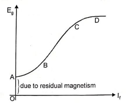
When the field current is zero, there is some flux due to residual magnetism and this causes a small induced emf. It is shown in figure above as OA.
As the field current is increased, the induced emf increases, increasing linearly from A to B. As the field current is further increased, the increase in flux is much smaller and hence the emf also increases slowly. At point D saturation has set in and any further increase in field current does not produce any increase in induced emf.
Internal and External Characteristics
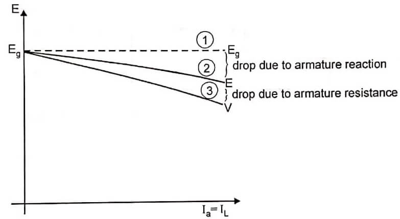
The curve (1) can be drawn, armature current versus no load induced emf. It is for ideal dc generator only. There is no voltage drop in generator.
Internal Characteristics
This curve is drawn between the emf E actually induced in the armature (after allowing for the demagnetising effect of armature reaction) and armature current Ia. Here by increasing the armature current induced emf E will decrease due to armature reaction. This curve is called internal characteristics or total characteristics. This is curve (2), indicated in figure.
External Characteristics
This curve is drawn between the terminal voltage (voltage across load) and armature current. Here by increasing armature current or load current, the induced emf again decreases due to armature resistance. This curve is called external characteristics or voltage regulation curve. This is curve (3), indicated in figure.
DC shunt generator characteristics
In the discussion on OCC curve above, the field was connected to a separate d.c source. We may now ask, if d.c voltage is obtained from the armature of the generator can we use this voltage to supply the field, thus eliminating the need for a separate d.c source.
The answer is yes, we may use this voltage for the field. The induced emf will depend on the field current and at the same time the field current will depend on the induced emf. It is nothing but self excitation. Since the armature and field windings are connected in parallel, it is called shunt excitation. Figure shows dc shunt generator.
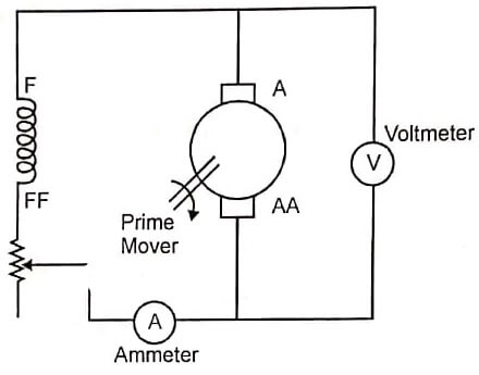
Here, the generator speed is constant. Figure shows open circuit characteristics of a dc shunt generator.

Initially the field current is zero, but emf (OA) is induced in the generator due to residual magnetism. Due to this voltage field current increases and emf also increases. The emf and field current progressively increase till it reaches point B. At this point, the field current is just sufficient to produce the voltage B. There is no further increase in field current or induced emf. This curve can be drawn from field current and induced emf. This curve is open circuit characteristics.
Critical Resistance (Rc)
OR is the tangent drawn to the linear portion of O.C.C from origin. The slope of this tangent OM/ON gives the value of critical field resistance, when the generator just excites.
Conditions for build up of a self excited shunt generator
- There must be some residual magnetism.
- For a given direction of rotation, shunt field coils should be properly connected to the armature terminals.
- Shunt field resistance should be less than the critical resistance (when excited on open circuit).
Internal and External Characteristics (or) Load Characteristics
shows the connections for a d.c shunt generator. The field current Ish the armature current Ia, and the load current IL are related by the equation.
Ia = Ish + IL
The armature has to supply both the load and field circuits.
Once the generator has built up to the specified voltage on no load, it may be loaded. What happens as we increase the load on the generator? The load current IL increases and this implies that the generator current (armature current) also increases. It will also be found that while the induced emf Eg remains constant (if speed and field current are constant), the actual voltage available at the generator terminals for supplying the load reduces. This voltage is called terminal voltage and there are several reasons that cause its reduction.
- As we start loading, Ia increases causing a drop of voltage in the resistance of the armature Ra.
- Drop in the brush contact resistance.
- Drop due to armature reaction. [When the load current flows in the armature conductors, a flux is produced. The armature is now under the influence of two fluxes. The main flux produced by the field and armature flux produced by the current flow].
The above three factors cause a decrease in the induced emf. The above discussion can be expressed by the following equation.
V = Eg (Drop in armature resistance + Brush drop + Drop due to armature reaction)
Fig shows internal and external characteristics of dc shunt generator.
The curve (1) shows ideal dc generator i.e., by increasing load current the terminal voltage should be constant. There is no drop in the armature. i.e Eg = V The curve (2) shows internal characteristics, here the drop is due to the armature reaction. The curve can be drawn for load current versus E. The curve (3) shows external characteristics. Here the drop is due to the armature resistance. By increasing the load current the terminal voltage decreases. It is shown in figure.
V = E – Ia Ra
DC Series Generator Characteristics
The connection for the dc series generator is shown in figure.
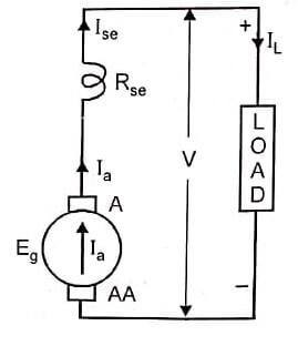
In this case, it is easily seen that Ia = Ise = IL
Figure shows O.C.C, internal and external characteristics of series generator.
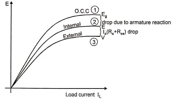
The curve (1) shows open circuit characteristics. This curve can be obtained by disconnecting the field winding from the machine and excited by separate d.c source. The curve (2) shows internal characteristics. Here, the drop is due to armature reaction. By increasing the load current, the induced emf E decreases. The curve (3) shows external characteristics. Here, the drop is due to armature resistance and series field resistance. This curve can be drawn from load current versus terminal voltage. By increasing the load current, the terminal voltage decreases, as V = E – Ia (Ra + Rse)
Compound Generator
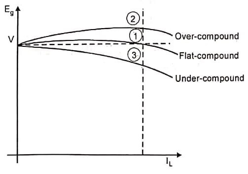
Figure shows the connections for a compound generator. It consists of series field and shunt field windings. Figure shows external characteristics of compound generator.
Fiat Compound Generator
In a shunt generator we have seen that the terminal voltage falls on loading, whereas in a series generator the terminal voltage increases with load. A compound generator has both shunt and series fields and if the drop in flux in the shunt field is exactly compensated for by the rise in flux in series field, then it is possible to have constant voltage characteristics as shown in figure (curve1). This is called flat compound or level compound generator. Here by increasing the load current the terminal voltage is almost constant. Eg = V
Over Compound Generator
Curve (2) shows the characteristics of over compound generator. Here the series field excitation is more than shunt field. Therefore by increasing the load current, the terminal voltage also increases. It is known as over compound generator. V > Eg
Under Compound Generator
Curve (3) shows the characteristics of under compound generator. Here the series field excitation is less than the shunt field. Therefore by increasing the load current, the terminal voltage decreases. It is shown in figure. It is known as under-compound generator. V < Eg
| Read More Topics |
| Types of DC Generators |
| Reactive power and voltage control |
| AlterNet voltage regulator |


