Consider a transformer arrangement as shown in figure.
N1– Number of primary turns
N2 – Number of secondary turns
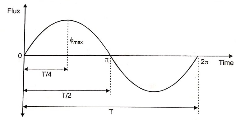
Φm – Maximum value of flux in the core in wb
Bm – Maximum value of flux density in the core in wb/m²
A – Area of the core in m²
f – Frequency of the AC supply in Hertz.
V1 – Supply voltage across primary in volts
V2 – Terminal voltage across secondary in volts
I1 – Full load primary current in amperes
I2 – Full load secondary current in amperes
E1 – Emf induced in the primary in volts
E2 – Emf induced in the secondary in volts

Since applied voltage is alternating in nature, the flux established is also an alternating one as shown in figure. From figure it is clear that the flux is attaining its maximum value in one quarter of the cycle i.e., T/E sec where ‘T’ is the time period in second.
We know that  where ‘f’ is the frequency in Hz.
∴ Average rate of change of flux 
If we assume single turn coil, then according to Faradays laws of electromagnetic induction, the average value of emf induced / turn 
From factor  (Since Φm is sinusoidal)
∴ RMS value = Factor × Average value
∴ RMS value of emf induced / turn = (1.11) × (4f × Φm) = 4.44 f Φm volts
∴ RMS value of emf induced in the entire primary winding
E1 = 4.44 f Φm × N1 or
E1 = 4.44 f Bm AN1 volts
Similarly RMS value of emf induced in the secondary E2 =4.44 f Φm N2 volts
or E1 = 4.44 f Bm A N2 volts.
| Read More Topics |
| Transformer construction and working |
| Electrical braking of DC motor |
| Types of DC generator |
| Electrical potential and e.m.f |


