Types of fixtures are used to hold the workpiece during machining operations. The name is derived from the fact that a fixture is always fixed or fastened to a machine in the fixed position. It does not contain arrangements for guiding the tool. The use of fixture becomes essential when the components to be produced are in a larger number.
Some types of tooling used in positioning parts relative to each other for fabricating purposes are also commonly referred as fixtures. Few examples of this type are assembly fixtures, welding fixtures.
There are many number of fixtures used in different Industries for different types of workpiece. But generally, they are classified on the basis of their working operations in different machine tools. In a setup using fixture, the responsibility for accuracy depends upon the operator and the construction of the machine tool.
Types of Fixtures
Plate Fixture
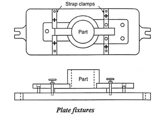
Plate fixtures are the simplest form of fixture. The basic fixture is made from a flat plate that has variety of clamps and locates to hold and locate the part. The simplicity of this fixture makes it useful for most machinery operations. Its adaptability makes it popular.
While the basic appearance and style of a plate fixture are similar to those of a vise-held fixture, the main difference between these two is the work piece size. Plate fixtures are designed to machine larger, heavier parts than vise-held fixtures.
Designing a plate fixture
The first step in designing a plate fixture is assembling and analyzing all relevant data concerning the part to be machined. Once a plate fixture has been determined to be the most economic and efficient fixture to use for the operation, the designer begins to analyze specific information about the part to form design ideas.
- The part is a rough casting approximately.
- The approximate wall thickness.
- The part has no prior machining.
- The material is cast aluminum.
- The operation required is to gang milling the surface.
- The fixture is for production run.
- The blank is received in it cast condition.
Using this information, the designer begins to design the plate milling fixture.
Locating the part : According to the part drawing and designer notes, the work is located and clamped on machines using fixtures.
Supporting the part : For supporting the part, a combination of fixed and adjustable solid support is provided sufficiently.
Clamping the part : The part is clamped using four cam-action clamp called four cam – action strap clamp. These are position on each side. Cam clamps are again selected for their fast action.
Locating the cutters : To accurately position the cutters, the machine operator should use a trial act method to locate the cutters properly.
Angle Plate Fixtures
It is a variation of the plate fixture. With this tool, the part is normally machined at a right angle to its locator. While most angle- plate fixtures are made at 90° there are times when other angles are needed. In these cases, a modified angle-plate a fixture can be used.
Designing an angle plate fixture : The following factors must be considered while designing the fixture.
- The part is a rough casting approximately.
- The part has a machined base with four 10mm holes.
- The material specified is a cast brass.
- The fixture is for production run.
- The operation required is boring.
- The part received for this operation has been milled and drilled on the bottom surface.
- The part has a cored a hole of 20mm diameter approximately
Locating the Part – Types of Fixtures
The most accurate and efficient method to locate this part is by the holes in its base. Assuming the part received for the boring operation is drilled without excessive variance from the specified size, the locators used should be the solid type. One round and one diamond pin will accurately position the part provided the pins which are positioned correctly.
Clamping the part – Types of Fixtures
To keep the cost as low as possible, a strap type clamp is selected for this casting. The strap is the latch type which pivots on end and latches on the other. The screw used to reduce the possibility of injury from exposed threads.
The material specified for this tool should be cast bracket material in an angular form. Locating the tool body to the faceplate, it is to be mounted on many ways.
The simplest and easiest method is to provide a boss on the backside. of the angle plate, which will fit the center hole of the faceplate. The bolts should be counter balanced to reduce vibration and smooth rotation of the faceplate in the case of larger tools.
Vice Jaw Fixtures
These fixtures are used for machining small parts with this type of tool; the standard vise jaws are replaced with jaws that are formed to fit the part. Vise-jaw fixtures are the least expensive type of fixture to make. Their use is limited only by the sizes of the vises available.
Multi station Fixtures
Multi station fixtures are used for primarily high speed, high volume production runs, where the machining cycle must be continuous. Duplex fixtures are the simplest form of multi station fixture using only two stations. This form allows the loading and unloading operations to be performed while the machining operations are in Progress. For example, once the machining operation is complete at station 1, the tool is revolved and the cycle is repeated at station 1 and also a fresh part is loaded.
Profiling Fixtures
These fixtures are used to guide tools for machining contours that the machine cannot normally follow. These contours can be either internal or external. Since, the fixture continuously contacts the tool, an incorrectly art shape almost shows how the cam is accurately cut by maintaining contact between the fixture and bearing on the milling cutter. This bearing is an important part of the tool and must always be used.
Lathe Fixtures or Turning Fixtures
It is a quite easy to hold regular shaped workpiece on lathes in standard work holding devices, such as chucks, collets, faceplate, mandrels, and on mandrels. But irregular shaped components offer a lot of difficulties in holding them correctly. The workpiece having complicated shapes has to be necessarily held in position with the help of turning fixtures. These fixtures are normally mounted on the nose of the machine spindle or on a faceplate and the workpiece is held on them. The following design points should be considered while designing a lathe fixture.
- The fixture should be accurately balanced in order to avoid vibrations while revolving. Whenever necessary, the fixture may have to be provided with counterweight or balance weight to balance the unbalanced force.
- Clamps and other holding devices should be designed in such a way that they will not be loosened by centrifugal force.
- There should be no projections of the fixture which may cause injury to the operator.
- The fixture should be light in weight as far as possible, since it is rotating.
- It should be carefully designed, to be rigid enough with minimum overhung, should grip the workpiece very firmly.
- The part must be mounted and held in such a way that there will be no obstruction in the way of cutting tool.
- Providing an adequate support for thin section of sections under pressure from lathe tools.
- Locating the workpiece on critical surfaces, from which all major dimensions and angular tolerances are taken.
- The fixture must be small enough so that it can be mounted and revolved without hitting the bed of the lathe for which it
is designed.
A lathe fixture consists of a base, location and clamping devices as usual and an arrangement for locating and fastening the fixture securely and accurately in the lathe. Some of the lathe fixtures are described below.
How are face plate turning fixtures located?
Face plate turning fixtures are located on the face plate by means of two dowel pins and secured by T-bolts inserted into T-slots in the face plate.
Faceplate Turning Fixtures
This is a common type of turning fixture which is usually fastened to the lathe faceplate or back plate. It is usually located on the faceplate by means of two dowel pins and secured by T-bolts inserted into T- slots in the faceplate. The bore on the lathe faceplate receives a fixture back plug to locate the lathe fixture on the lathe spindle centre line. The fixture body is designed to drill a hole in the face of a cubical shaped workpiece.
| Read More Topics |
| Exhaust Gas Recirculation EGR |
| Evaporative Emission Control System |
| Underfeed Stokers Classification |
| Overfeed Stokers Classification |
| Mechanical Comparators |